POSITIONNER AND INDICATOR FOR BOW
PROPELLER Fr Be nl
 The
action of positioning the button of the instrument in the desired
direction
by turning to either side drives the direction motor of the bow
propeller
through the action of the relais until the bow propeller reaches the
same
angle as the instrument button. No reason to wait as in the ordinary
systems
because the bow propeller vertical (Z) axe stops turning when the
desired
position maches on both sides. The turning movement of the bow
propeller
is visible on the leds indicator on the instrument panel that follow
its
movement.
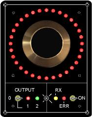
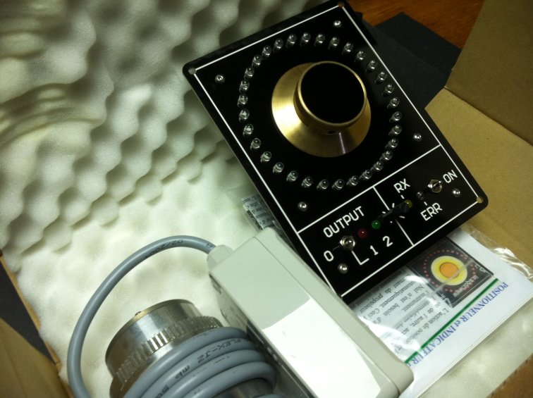
The complete instrument concists in a panel
indicator with
positioning
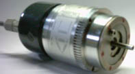
button for the wheel house side and a axial position sensor (encoder)
mounted
on the vertical (Z) axe of the bow propeller. The electric connection
between
the angle position sensor and the instrument panel is made by a
standard
electric cable with three conductors. 3x0.35mm² is enough for 100
meters. (±300f).
Note that the axis of the position sensor (encoder) can turn in any
direction without limitation. Its axis must be mechanically coupled
with
the vertical axis of the bow propeller with a ratio of 1/1. This way
they
will rotate both at the same angle.
The panel should be installed on the dashboard or in a place insuring
good access to the positioning button while mameuvering.
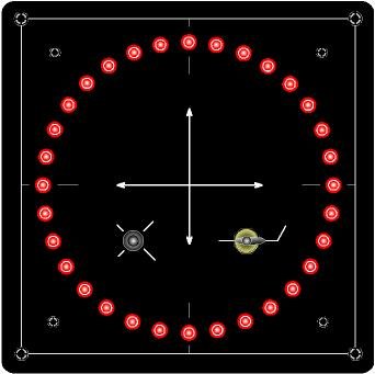
The indicator has a
definition of 32 positions (segments).
The position sensor (which is a real Absolute encoder *) transmits
the actual position of the bow propeller Z axis to the panel. This
position
is permanently indicated on one of the 32 led's. The position of the
positioning
button is at the same time indicated by flashing one of the 32
corresponding
led's. When a difference occurs between the two positions (eg: while
turning
the button) one of the two relais is switched on to drive the position
motor of the bow propeller Z axis. This until the bow propeller
position
becomes the same as the positioning button. The instrument then acts as
a servo**.
The positioning button is designed with optical, digital technology
and therefore does not contain any brushes or moving contact.
The two relays of the instrument panel are able to switch the power relays of the bow propeller direction motor or hydraulic valves. These two instrument panel relays are to be connected on the stick (if existing) which was already used to control the direction motor. This way a double command system is available. The two relays of the instrument panel have a two lead isolated output. They act as a switch and close the circuit (contact) when active. They can drive a current of 5 Ampere.
Obviously, the bow propeller must be equipped with an electric
motor
to make its vertical (Z) axis turn if you want to use the instrument
as a positioner. But the instrument can also be used only as an angle
position indicator without connecting the relays.
The instrument panel must be powered by the board accumulators, 12 or 24 volt systems. The two relays are standard for 24 volt systems and should be replaced if used, to work on 12 volt systems. The position sensor (encoder) is powered through the same cable it uses to transmit the position information.
One can simplify the functioning with the following procedures:
-The position sensor transmits the actual bow propeller Z axis angle
to the instrument panel.
-The instrument shows the actual angle on the indicator (leds).
-The instrument calculates the difference between the angular position
of the positioning button with that of the bow propeller Z axis. If
needed,
its switches a relais in order to set the bow propeller Z axis at the
same
angle as the command button of the instrument panel through the action
of the bow propeler direction motor (see also the video).
Back
to panels previous
*Absolute encoder:
 There are two current types of axial encoder.
Incremental encoders
and absolute encoders.
Incremental encoders also report the change in
shaft
angle position but need a mechanical and software start-up procedure.
However,
this
information will be lost by over-speed and/or fast/strong vibrations of
the shaft and at each power down.
The ABSOLUTE position encoder here
used,
does not have those disadvantages and always knows its position at
power
up and by any change of its angle axis. The 360 degrees output per
revolution
is divided in 32 physical segments to match the positioner panel.
**Servo: System that accomplish a certain task while comparing the order given (action = positioning buton) to the movement or motion its generates (retroaction, feed back = position encoder).
 POSITIONNEUR
et INDICATEUR pour PROPULSEUR D'ETRAVE
L'action de positionner le bouton de l'instrument sur la direction voulue en le tournant d'un côté ou de l'autre, actionne automatiquement le moteur de direction du propulseur d'étrave par l'intermédiaire des relais, jusqu'à ce que le propulseur d'étrave ait atteint le même angle que le bouton de l'instrument. Nul n'est besoin d'attendre, comme dans les systèmes habituels, car le propulseur d'étrave s'arrête à la position choisie automatiquement. Ceci prend une grande importance pendant les manoeuvres. Le mouvement tournant du propulseur d'étrave est visible sur les Dels (Diodes-Electro-Luminescentes) de l'instrument qui suivent son mouvement, jusqu'à ce que l'angle choisi soit atteint.
L'instrument comprend un encodeur absolu et une plaque indicateur positionneur. L'encodeur, ± 8x6cm, est à monter sur l'axe vertical du propulseur d'étrave et son axe doit parcourir le même angle que celui du propulseur d'étrave. La seule pièce mobile de l'encodeur et son axe monté sur deux roulements à billes. Le rapport de leur couplage est donc de 1 sur 1. Ils parcourent donc ensembles le même angle de rotation à chaque mouvement. La plaque, 16x12cm, est à installer au tableau de bord, son bouton positionneur devant être au mieux accessible pendant les manoeuvres. L'instrument se raccorde à l'encodeur avec un câble électrique fin à trois conducteurs. 3x0.35mm de section est suffisant pour une longueur de câble de 100 mètres. ( testé à 200 mètres )
L'indicateur a une définition de 32 positions (segments). Le senseur axial monté sur le propulseur, un véritable encodeur absolu*, transmet l'angle actuel du propulseur d'étrave à l'instrument. Cet angle ou position est alors indiqué par une des 32 dels de façon continue. Quand à la position du bouton est elle, indiquée en même temps mais de façon discontinue en faisant clignoter une des 32 Del correspondante. Si une différence apparaît entre les deux positions du fait d'actionner le bouton positionneur, un des deux relais est actionné afin de commander le moteur de direction du propulseur d'étrave. Ceci jusqu'à ce que la différence de position s'annule. L'instrument se comporte alors comme un servo**. Le bouton positionneur est conçue avec une technique optique et digitale.
L'instrument comporte 4 voyants (dels) de contrôle. Une verte et une rouge, en bas à gauche, qui indiquent le fonctionnement des relais. Une jaune, en bas à droite, qui indique chaque informations venant de l'encodeur. La rouge, à côté de l'interrupteur M/A qui indique en même temps que le buzzer audible d'alarme, une anomalie eventuelle. Cette dernière peut être le non fonctionnement du moteur de direction, de l'encodeur ou du bouton de direction. L'interrupteur de gauche et pour annuler l'action des relais, donc mettre l'instrument en fonction indicateur seulement.
Les deux relais commandent le moteur de direction du propulseur par l'intermédiaire de ses relais ou de ses vannes hydrauliques électriques habituels. Ils sont à connecter à la commande manuelle (manette) qui était en service avant d'installer le positionneur. S'il y en avait une, il est avisé de laisser la manette en place afin d'avoir la double commande, parfois requise. L'instrument peut aussi être seulement utilisé comme indicateur de position. Il s'installe alors de la même façon à la différence des relais qu'il n'est alors pas nécessaire de connecter. Les deux relais de commande de la plaque ont une sortie isolée à deux pôles qui ferment le contact quand le moteur de direction doit tourner. Ils peuvent supporter un courant permanent de 5 Ampère. Ils peuvent se brancher directement aux connections de la manette si le courant reste dans la limite admise de 5 Ampère. La manette (si présente) et les relais de la plaque de l'instrument positionneur servent à commander des relais de puissance généralement montés à l'avant à proximité du propulseur d'étrave. L'instrument est alimenté par la batterie de bord de 12 ou 24 volt DC. Les deux relais montés sur l'instrument sont standard pour 24 volt. Pour 12 volt il faut les changer par deux relais 12 volt. Le senseur de position d'angle est alimenté par son propre câble, celui qui le raccorde à l'instrument.
On peut simplifier le fonctionnement aux procédures suivantes: - Le senseur de position d'angle transmet l'angle actuel à l'instrument, de l'avant à l'arrière. - L'instrument affiche l'angle actuel sur les leds. - L'instrument calcule la différence entre la position angulaire du bouton positionneur à celle du propulseur d'étrave et actionne si nécessaire un des relais afin de positionner le propulseur d'étrave au même angle que le bouton de commande de l'instrument (voyez le video). Retour à la page précedente
* Encodeur absolu: Il
existe deux types courant
d'encodeur;
incrémental et absolu. Le premier a le désavantage de
perdre
l'information de position à chaque coupure de courant et
nécessite
donc un cycle de ré-initialisation avant chaque usage. Ceci
consiste
à tourner son axe jusqu'à une position connue (index) et
d'effectuer un comptage d'impulsion afin de déduire la position
actuelle.
Le deuxième, de type absolu et celui employé avec
l'indicateur (et aussi le positionneur), a l'avantage de
connaître
instantanément sa position à la mise sous tension et
à
chaque mouvement de son axe.
** Servo: Système qui effectue un certain
travail
en comparant de manière quasi immédiate l'ordre qui lui
est
donné (action = bouton positionneur) au mouvement qu'il effectue
(rétroaction ou Feed back = senseur axial).

 POSITIONNEUR en INDICATOR voor BOEGSCHROEF