G GSM netwerk parameters
De meest rechtse transparant-rode LED op positie (54)
(zie nummers op de controller deksel) geeft aan dat de SIM-kaart is
aangemeld bij het GSM-netwerk via de radio module als het knippert met een korte flits om de twee seconden.
Een korte flits elke seconde of korter
geeft aan dat het systeem geen SMS kan ontvangen of verzenden. Gebruik
dan het internet indien aangesloten of de seriële verbinding naar de PC
via de optionele seriëelkabel.
Houd altijd de SIM en de SIM-houder vast aan de plastic randen en niet bij
de contacten om mogelijke statische ontlading te voorkomen...
Redenen dat er geen SMS-verkeer mogelijk is, zou kunnen zijn:
SIM is niet in de juiste houder, zet het in S1 voor SIM=1 en S2 voor SIM=2 of kies SIM=3.
SIM maak geen goed contact! Probeer de SIM een halve mm op en neer te
schuiven in de gesloten socket.
SIM of SIM-houder vies! SIM-kaart en -houder kunnen voorzichtig worden gereinigd met 90° alcohol.
Gebruik de meest eenvoudige SIM (geen 3/4G). Verwijder SIM pincode met een mobiele telefoon.
Command [Code G?] will show the
following parameters:
Pw SIM
1
SIM mode
1(defaut) selected with [Pw SIM 1]
Mode=1 Used=1 Selected
mode and the one actually used
0,1,2,3(1+2)
Possible
modes. 0, 1, 2 ou 3(two together)
Fg restart
GSM
radio! [0000 fg] reset and
reconnect to network
Fe Emergency Stop! [0000 fe] Stop radio
immediately!
Ant:
36%
Rx Antenna signal. < 12% become
very low!
OP: KPN
MOBILE Name of
actual connected cellular operator
IMEI: 563031015145201 International
Mobile Equipment Identity
V0:
4364
Voltage on GSM radio module
(millivolt)
T0: 33
Internal contrôleur temperature,
°Celcius
When the list is incomplete, use command [0000 G+] that will first make
reload the parameters before sending the above message.
Mode
SIM 0 will make the GXL88 controller to work without GSM
connectivity. So SIM cards (also inserted) are
ignored and all related GSM issues are discarded. This option will be useful when the
controller is used to regulate some local systems that do
not require external control or commands. When wanted,
internet or
PC serial connectivity is still available in mode SIM 0.
Regarding the
possibilities, this controller is also a programmable
control computer at very fair and competitive price!
Please note carefully that sending the command [Pw SIM 0] to the controller
via SMS enables the
SIM mode 0 and will consequently be the last SMS command
received via SMS. So if the internet mode (if
available) is not enabled before by [0000 i on]
the
controller will only be locally accessible via the serial link
to the PC.
[Pw SIM x
fg] where x
can be 1, 2 or 3, sent from internet PC via serial or internet
will re-enable GSM communication when possible.
Mode SIM 1 is for SIM
holder at S1 and Mode
Sim 2 for S2. Select preferably SIM1 at S1 for
controller having two SIM holders when only one SIM will be
used as in most cases.
So command [0000 sim 1]
enables SIM 1 usage and of course its SIM voice call
number! SIM mode 2 will be configured when
SIM holder S1 is bad or dirty. SIM 1 or 2 work both the same
and SIM 3 makes
use the first SIM available to connect to the GSM network.
H H:M setting for
time related functions.
To set the controller software and hardware Real Time
Clock (
needed for all related Time
functions) at 14:49, use [
Pw H 14:49].
The clock can be adjusted before or
after any other command. Like here with [Pw H 12:14 R1 Off s]
The software clock also tells about unexpected system resets.
Watchdog and control procedures will automatically reset and
restart the GXL88 microcontroller on fatal software errors. By
default and as control, a Status SMS is sent to number N1 3mn
after power on or initialize when no command is received within
those 3 minutes.
When the time shown in the status
is at 00:03, a system restart is notified! After that, the
software clock will synchronize with the hardware real time
clock
and automatically be set to
the right time if parameter
Hc is left at 0 and if
no power interruption has occured.
SMS [Pw
h?] to GXL88 lists all time related function settings.
Pw H 05:38
Actual
controller time set by [Pw H HH:MM]
Hs1 3 12:15 Status to N3
at 12H15 once a day
Hs2 1
00:10 Status to
N1 at xx:10 each hour
Hsm 0
mn Repetitive
status time synchrone to Hs1 N
Hss 0 sec
Repetitive
status SE at sec to HS2 N1 number
He1 6 00:00
Energy SE to N6. Répetitive (00:MM) or at HH:MM
HeM 22 mn
Energy
status SE to N6. Répetitive on 22mn
HeS 800
sec Energy status SE to N6.
Répetitive
on 800sec
HL 00:00
Status
to serial at HH:MM
HrA 4 08:30 20:13 R4 ON at
8H30 off at 20:13
HrB 5 22:45 07:03 R5 ON at 22:45, stop at 07H03
Hc 0 Hg
15 Clock ±s in Mode SIM 0. GSM test time
Status message sent from the function H will show its source as
hs1, hsm, etc, at Hxx
after the controller time line (see at s?).
[Pw Hs1 Nn 12:15]
Will force a Status SMS to Nn (that can be 1 to 35), each day,
at 12:15. [Pw Hs2 30 01:30] will send
a second status message to N30
at given time, so here each night after midnight at 1 hour and 30 minuts. Both cases need a
valid number at position pointed numbers list position.This will
give a good daily control of the system.
[Code HS1
2 00:15] make the status to number N2 each hour at minutes =15. This simply because
the HH field is left equal to zero!
Hs2 can do the same
and both functions can be used simultaneously to get two status messages per
hour.
So command [Code HS1
1 00:15 hs2 1 00:45]
could make send two
status messages each hour to N1.
Status SMS are sent synchronized to the minutes of the time with
Hsm function. Hsm uses the Number programmed at Hs1.
[Pw Hsm
11] sends a status SMS at xx:11 , xx:22, xx:33, xx:44 and xx:55 at number written at
Hs1.
[Pw Hsm
25] sends a
status SMS at xx:25 and xx:50 also at number
programmed at HS1. (Hsm >2 <59mn)
Hss force sends status
at Hss programmed
interval value to the number pointed by HS2 N in the number
list.
So command [Pw Hs2 25 00:00 Hss 600]
will send the status at number found at position 25 in
number list. This on the 10 mn here, but programmable from 1
to 65000sec. Writing 0 at "25" or "600" stops the function
Hss and Hs2 will be ignored because 00:00 is invalid.
An interesting option for Hss
will also be the possibility to send the status "ss" from
V1. Status [s]
form R1 is sent if value sec of hss is even and status
[ss] from V1 if odd. Please see [s] and [ss]
again above about the status messages.
[Password HE1 6 15:31] force
reads the Power Meter and then sends an Energy Status SMS [SE] to Number 6 in list. In this example every day at
15:31. If field HH of HsE is zero, only the minutes
are worked out and the [Se] status will be sent out once
each hour at MM = Minute of the controller enabled time
clock.
So [Pw HSE 8 00:35] makes send
each hour at midnight
and 35 minutes to
number written in the
phone book(number list) at position 8. (See at bottom the functions expert for the commands
[Se], [Sx ]and [Si] to the controller making it read/setting
the Power Meter.
Hem has the same synchron
functionality as Hsm above.
However the differences are that the message will be an Energie status [SE]
and that it will be sent
to the numbers indicated by HE1. See at
Hsm for He1 same timing). Parameters Hsm and Hem can be programmed with a value >2mn and < to 59mn.
Command [Hra 2 14:15 14:30] will make
switch R2
output at 14:15 On, and then
switches Off at 14:30 everyday. Function HRB
has the same functionality and here also could be used simultaneously on the
same relais output to get more
switching times.
So [Code HrA 1 00:15 08:45 HrB 1 14:00 17:15
h] could make switch same relais N1 at different
times.
See
also the function "Klignoteur"
that can switch
very short time on big delays.
Hc is a clock correction
parameter that can be used to
tune
the software clock only. If one thinks that the clock
is too fast with 2s every days, the command [
Pw Hc -2] can be used. For 4s a
day too slow, use command [
Pw Hc 4].
Parameter
Hc can better
be left to 0 (zero) when the SIM mode parameter is not zero, so
that the
software clock
will automatically synchronize with the
Real
Time
Clock that does not require
any correction.
The hardware
RTC is ignored while in SIM
mode 0 and only t
he software clock
will then be used, no matter the Hc parameter value. The default setting of Hc
is 0 and SIM is 1. (see
G? for the different SIM
modes).
Whatever the H
parameters settings are, the Clock(s) can always be set to
the wanted time when adding [ H HH:MM
] before or after an
other command sent to the controller. Care should be taken
so that here too, the command that makes return an answer
is the last in the command line. So for example here; [Password N4
020452444 R1 Off
H 17:51 ss].
The hardware RTC will normally take its power from inputs: BATT V1(31), ADAPTOR
VS(29) and L3/V3 at position (37) of the box. As for some
customer's needs, a CR2032 3V lithium battery can be
inserted in the internal and optional receptor in order to
move the controller without losing the HH:MM time.
Hg tells at which
rate the GSM network connection
control is done. Here at 11 and synchronous to the
minute. Hg can best be
left to this default value, but users can change it when wanted
with [Pw Hg MM].
Finally for menu H, any number index left at 0 or pointing to N33 will
make the function use GPRS and not SMS when transmitting the
corresponding message at programmed H timings. Please see the functions
expert file for details!
Internet Configuratie en Toegang. [Pw i?] Voor SMS info's. list
Sneller en eenvoudiger dan met alleen SMS kan de GXL88 op voordelige
wijze worden bediend via internet. Bijna alle functies, parameters en
instellingen zijn dan zichtbaar op één computerscherm. Het systeem
kan simultaan werken via internet en SMS.
Toegang via internet is mogelijk met de browser of internet navigator van
uw keuze. Het controller-internetadres dient u in de
adresbalk van de navigator te schrijven, zoals bijv:
http://53.123.234.50:1425/Page_name 1425 of anders is de PORT en Page_Name (optioneel) de
naam van de pagina. Beide parameters door u te < >kiezen.
Een vast IP-adres is sterk aan te bevelen, want natuurlijk moet het
adres (waar te verbinden om toegang te krijgen tot de controller via
internet) bekend zijn! Als u een dynamisch IP-adres heeft, zal het vaak veranderen.
De standaard poort is reeds
1425 of
1453 geconfigureed in de GXL88
ingebouwde M53 internet module. Het kan worden gelezen en veranderd
via ez-manager. Als de Page_Name is geprogrammeerd, zichtbaar met SMS-command [
0000 i] aan de controller, moet het ook worden gebruik na de 'slash'/ in de url.
Zoals gezegd, hoeft geen specifiek programma of applicatie te worden
geïnstalleerd om de controller te kunnen bekijken via internet vanaf elke
PC of
mobiele. De controller's interne internetserver zal een
webpagina maken die in alle browsers getoond kan worden.
Ontwikkelingen werden gemaakt met Firefox, SeeMonkey en Safari, maar
ander navigators kunnen worden gebruikt met minder(IE) of meer gemak (zelfs de
oude goede Netscape!).
Het is aan te raden om er voorlopig voor te zorgen dat het GSM-SMS-verkeer met de
controller werkt, vóórdat u de instellingen via
internet. Als de toegang via het internet onmogelijk is geworden vanwege
onvoorziene omstandigheden of gewoon omdat een verkeerd configuratiecommando werd
gestuurd, kan de configuratie hersteld worden via SMS.
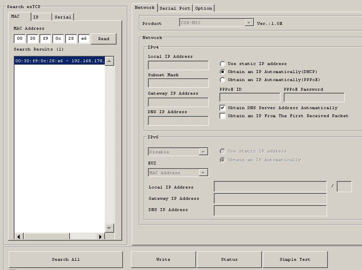
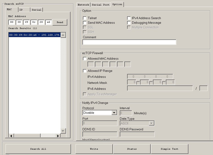
De ingebouwde internetmodule zal eerst worden geconfigureerd via de
ez-manager. Windows programma. EZ-manager hoeft alleen te worden gedownload en behoeft geen installatie. Zie en lees eventueel de webmodule-
documentatie, maar bestudeer vooral de drie standaard configuratieschermen
1, 2 en 3 die als
modeel kunnen worden gebruikt met ez-manager.
Ez-manager zal het
LAN- adres
(=local) toegewezen door de router, weergeven.
Dwing de router bij configuratie altijd hetzelfde lokale adres toe te
wijzen aan de controller-internetmodule, zodat u de controller ook altijd op het lokale netwerk kan bereiken.
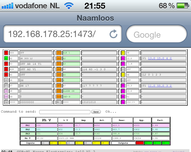
Voorbeeld van het te schrijven lokale adres in de adresbalk van uw browser:
http://192.168.178.40:1425/Page_name of (vanaf versie V2-17):
http://53.123.244.50:1425/-0000 ss SMS op scherm via internet (zie onder #).
[Code i] maakt een lijst van de internetinstellingen van de controller:
iCA 88.160.241.20:1425 GXL88 IP-adres:poort na de ":" *
iSA www.nnnn.com/name Adres te verbinden in client-modus
IPN Page_Name Naam van de interne internetpagina
ISL NO_NAME GXL88 User name in client-modus
iSW no_pass Acces Wachtwoord client-modus
iPR 0 Optioneel, page auto-refresh (reload xx)
iPT 0 Verbinding met de server time-out
2x<32 3x<16 >10s >5s Parameters lengte van ICA tot IPT
iPB 7 GXL<=>M53 comm. 7=57600 standaardi ON Zegt als internet function is ON, i1 of OFF. Ex: [Pw i on]
Alleen IPB op 7 (is al standaard
ingesteld) is noodzalelijk om de controller te laten werken via
internet met de M53 module. Dit, omdat al deze settings ook direct op internetmoduleniveau gedaan kunnen worden met
ez manager.
De internetmodus wordt gestart met SMS: [Pw i on].
ICA: de niet-noodzakelijke
Internet
Controller
Address parameter zal worden
gebruikt door de command [
Reload 0]. Dus als
ICA nog niet is
geconfigureerd, zal het adres handmatig in de brouwseradresbalk
geschreven moeten worden om
de grafische representatie van de controller te zien op uw scherm. Gebruik anders ook de [
Send] (ook met een lege command lijn). [Send]
gebruikt alleen het adres in de adresbalk als bestemmingsadres.
* ICA parameter is
alleen nodig voor het navigatorscherm (rechtsonder) commando "Reload 0".
ISA,
optioneel, is het server-adres waar de controller verbinding zal
maken wanneer de internet-module en de controller beide zijn
geconfigureerd in client modus. Deze (advanced) modus is simpelweg de
inverse van de normale modus wanneer de browser (client) de
internetpagina aan de controller (server) vraagt. Het principe is hetzelfde
als de GPRS-modus die via het GSM-netwerk loopt, maar dan via de router en
het Internet.
Eventueel kan een isl-identificatienaam en iSW-wachtwoord
voor toegang tot de server worden geconfigureerd . iPT is de toegestane tijd te
wachten voor verbinding met een server, vóór het annuleren van de
transactie.
De niet-noodzakelijke
IPN-parameter, de "Page_Name", is de naam van de
internetpagina gegenereerd door de GXL88 controller en verzonden naar
uw navigator scherm.
Samen
met IP:Port/Page_Name maakt dit het unieke adres waar
te verbinden naar de controller. Deze pagina naam is standaard
"Page_Name" of "GXL88" of ongeprogrammeerd (niets) bij startup. Dit is te
controleren met command [
0000 i]. Geen spatie in het adres en de naam. Gebruik hier maximaal 15 alfanumerieke tekens (letters+cijfer). De controller
differentiëert hoofdletters en kleine letters in de paginanaam en dus moet dat
precies worden gespeld.
Als u de paginanaam wilt verwijderen, stuur commando [
0000 IPN ] en noteer
hier de standaard spatie na de opdracht (IPN ), en daarna de tweede
spatie die de paginanaam doet verwijderen. Controleer nadien met SMS-command
i? aan de controller. U kunt dan alleen gebruik maken van
IP:Port zoals;
http://53.123.244.50:1425 om de controller zonder paginanaam te bereiken.
iPR kan op sommige browsers automatisch de pagina doen herladen.
Bijvoorbeeld command [
0000 ipr 30] zal de pagina om de 30
seconden
vernieuwen. De parameterwaarden worden weergegeven
in de
rechter benedenhoek naast "
Reload" die standaard op 0 (nul) is. Programmeer deze niet te
laag, met een minimum van ongeveer 10.
Indien er geen verbinding wordt gemaakt, is een lege pagina ook het
resultaat van de reloadfunctie! Gebruik dan uw browser terug-knop om terug te keren naar de
laatst weergegeven pagina en verhoog de waarde van de reload parameter
IPR. Toch kan dit het best
op 0 (nul)
worden gelaten tot gewend is aan de soms onverwachte reacties van de browser,
controller en internet. Handel kalm en klik niet te snel en herhaaldelijk
op de reload- of send-knop, omdat het internet en vooral de controller enige
tijd nodig hebben om commando's uit te voeren (dit dus ook met GSM-verkeer).
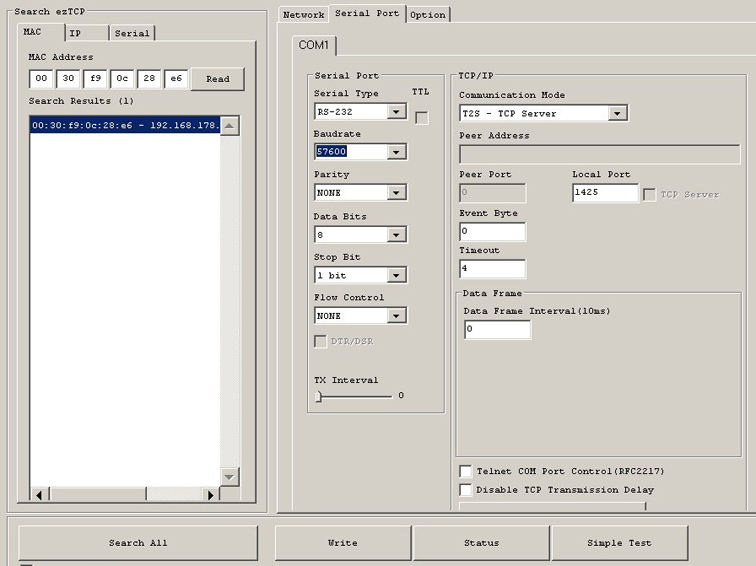
iPB is de "baudrate" parameter en stelt de communicatiesnelheden
tussen de microcomputer van de controller en de internet IP-module in.
IPB 47 (9600B/s) zal
worden geconfigureerd voor een langzame internetverbinding. De tweede [
Pw IPB 7] (57K6) is de standaard instelling en
is te gebruiken voor gewone ADSL-aansluitingen. Tenslotte [
Pw
IPB 3] (115K2) (kan worden gebruikt voor LAN), maar geeft alleen goede resultaten op zeer snelle internetverbindingen.
In alle drie de gevallen zullen wij
eerst met ezManager de (M53 of
andere) Ip module via LAN lokaal configureren. Bij tabblad " Serial Port
/ Baudrate " en daarna parameter
iPB via SMS of het
PC programma. Zorg ervoor dat in
ieder geval dat de SMS-modus of de PC-modus werkt om configuraties die
onbedoeld worden veranderd te kunnen herstellen.
Klein verschil: Proberen te verbinden met een foute IP: poort zal "site
not found" aangeven en met de juiste IP: poort, maar foute paginanaam
"verbinding reset" aangeven.
De UTP, RJ45, of netwerkkabel genopemd, dient te worden aangesloten op
de controller RJ45-connector die automatisch
zowel gemarkeerde als crossover of patch of een rechte kabel
accepteert en detecteert .
De LED's van de RJ45-connector vertellen over de staat van verbinding met de
router en geeft een actieve verbinding
aan . Continu groen en geel
intermitterend knipperen betekent dat deze is ingelogd/geregistreerd op de router.
Beide LEDs, groen en geel continu brandend betekent dat de verbinding
actief is. Koppel de kabel los en sluit na een paar seconden
weer aan.
Observeer de LED's, die ook de offline-staat aangeven...
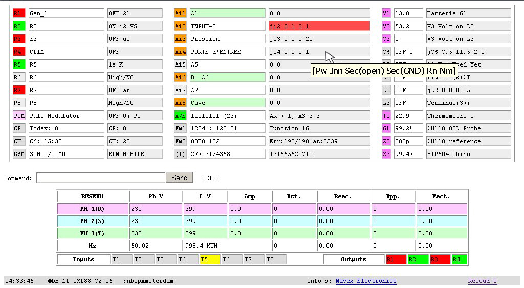
De webinterface geeft bijna alles zichtbaar op één scherm in één keer
en het passeren van de muis door een veld laat nog meer info's zien via de
tooltips. Toch zal wat oefening nodig om te wennen aan alle getoonde
informatie. Makkelijk genoeg is dat de opdrachtregel precies dezelfde
syntax als de SMS of PC opdrachten accepteert.
Zoals hierboven gezien, drukken op "
Reload 0" vereist de juiste
definitie van de parameters
iCA en eventueel
IPN. Knop [
Send], zelfs
met een lege opdrachtregel, zal de adresbalk van uw browser gebruiken.
Als de
PMC is aangesloten, worden de metingen bijgewerkt na de pagina
te hebben geladen met de "Reload" en niet door de opdracht [Send],
tenzij natuurlijk de command juist Se, Sx of Si was. De PMC is
zichtbaar op het scherm met parameter ACM >0 (1 tot 3) en de i/o indien ACi
>0. Zie voor meer over de
Power
Meter
Controller de "expert functies".
Internet en PC seriële modus kunnen niet tegelijkertijd worden gebruikt op de
GXL88. Om de PC-modus commando's te hervatten zal de internet modus verlaten moeten worden door de command [
0000 i off] te verzenden vanaf het internet of SMS naar de controller.
Pas op dat na I Off geen opdracht meer via internet verzonden kan worden!
De [
0000 i on]
command verzonden per SMS of PC herstelt de internet-modus. Zorg dat de
controller nog te bereiken is via SMS om onverwachte situaties te kunnen
herstellen, vooral wanneer de manipulaties op afstand worden gedaan van
veraf.
De controller aan de router aansluiten laat deze laatste automatisch
een IP-adres toewijzen aan de internet-module (DHCP). Het op de router
toegewezen IP-adres en de daar door u te configureren PORT*, hier bv:
1425, moet ook in de internetmodule worden toegewezen via ezManager om
in staat te zijn om lokaal(LAN) toegang te krijgen tot de controller met
LANipAddress/PORT/PAGE_NAME.
Om toegang van buitenaf via
internet
WEBipAddress/PORT/page_name contact met de controller te krijgen, zal in de router
een zogenaamde "Port Forwarding" moeten worden geconfigureerd zodat hij weet waar te verbinden op de LAN. De
zelfde
port moet zowel in de router-configuratie met de router webinterface geconfigureerd
worden als in de internet module via ez-manager.
Alleen indien gebruikt, kan de optionele small Internet module (24x20mm) op
zijn plaats in de controller worden ingeplugd. Wees zeer voorzichtig
(stroom uit) en let op de witte stip op de linker bovenkant van de
module en ook op die op de controller board.
Als het internet nooit wordt
gebruikt, maar alleen SMS of PC seriëel, kunt u de internetmodule werwijderen om stroom (en daarmee ook de interne temperatuur van de controller) te beperken... Deze module is niet
vereist als er geen LAN of Internet ooit zal worden aangesloten. Zet
ook de internet-parameter op Uit via command [
0000 i off] naar de
GXL88.
Observeer beide LED's op de UTP RJ45 connector die de werking en staat van de verbinding toont.
# Een nieuwe functie werd toegevoegd vanaf versie V2-17 vanwege onduidelijke gevallen van internetverbindingen, die geen correcte
grafische weergave
van de controller kunnen terug sturen (zoals op schepen met internet
via satelliet). Deze maakt het mogelijk om direct gebruik te maken van de
adresbalk om de commando's in te voeren, zoals u via SMS gewend bent:
http://WEBipAdresse/PORT/-Code (cmd).
Concreet en als bijvoorbeeld:
http://53.123.244.50:1425/-0000 ss
van uw browser naar de controller zal een extended-status bericht
(ook style SMS) direct op het scherm tonen, maar dan via internet...
Dus het schrijven van commando
ip/port/-0000 R2 22 i in
de adresbalk schakelt Relais 1 voor 22 sec en stuurt menu-info i terug.
Dit op het scherm zelf via internet, onafhankelijk van de sim-modus.
Alle commando's zijn toegestaan en een sim is niet nodig als de
internetverbinding stabiel is. Grafische en/of tekstuele
representaties kunnen ook samen worden gebruikt.
Het
-teken gevolgd door het paswoord en één of meer commands worden geschreven na de
laatste slash
/.
Pas op
dat de internetmodus niet uitgeschakeld wordt in SIM mode 0 (of
zonder werkende SIM) of anders zal de controller alleen nog bereikbaar
zijn met de PC-kabel via de seriële aansluiting. Deze kabel is normaal
gesproken niet nodig, maar is los te bestellen bij ons.
Hoe dan ook, de internet
modes of PC en GSM zijn allemaal compatibel en beide kunnen
gelijktijdig werken (dus niet de Internet-modus en PC seriële!). Men
kan zelfs wanneer sim-mode 0 wordt gebruikt, de gsm-modem en diens
functionaliteit herstarten met het commando "Fg" (zie F?).
Gebruikt in het begin de internet mode met een sim in de controller voor meer zekerheid.
Voor alle onderdelen Vn, Tn en Zn, kunnen de uitgangen worden aangestuurd en eventueel kunnen waarschuwingen worden gestuurd op de geconfigureerde JUNCTIES On- en Off-drempelwaarden. Alerts kunnen worden gestuurd op de minimum en maximum (</>), lagere en hogere geconfigureerde alert grensen. De Alerts-grenzen (</>) worden geconfigureerd onder
en boven de drempelwaarden die de normale werking van de functie
besturen en zullen een alert geven op een niet goed functionerend
automatisme of wanneer een storing optreedt...
alerts
zijn berichten die worden verzonden wanneer de geprogrammeerde waarden voor <(LOW) en >(HIGH) worden overschreden. Ze zijn opgezet met de functienaam gevolgd door de < en > parameters.
Dus voor V1 bijvoorbeeld en voor <11 en >14 volt dient u command [0000 V1 11 14] te gebruiken. Hetzelfde geldt voor Vn, Tn en Zn , die alle Alerts kunnen sturen. Een ontvangen Alert SMS begint met a)
Waarschuwingsberichten worden eventueel verzonden door de JUNCTIES, die vrijwel elke ingang automatisch kunnen schakelen en dus zo eventueel
er voor waarschuwen. Het bericht zal worden gestuurd naar de gekozen
nummers N1 tot N35. Een ontvangen Waarschuwing-SMS zal beginnen met w)
Merk hier op dat de GXL88 controller zeer flexibel zowel een waarschuwings-
als een alertbericht voor dezelfde gebeurtenis kan sturen. Dit wanneer gewenst
op dezelfde of verschillende gemeten en geprogrammeerde waarden.
Alarm De Alarmfunctie, wanneer geactiveerd met A On of A O+ of door de eventueel aangesloten switch "button" zal een alarm-SMS-bericht
sturen wanneer nodig. Alarmmeldingen beginnen met !ALARM!
Dus (en niet te verwarren tijdens controller setup) naast de status-, info- en configuratieberichten die hun op verzoek worden terugontvangen, kunnen we drie soorten berichten van de controller krijgen: waarschuwingen, alerts en alarm.
Oftewel, voor duidelijkheid: een w)aarschuwing, wordt veroorzaakt door de waarden geprogrammeerd in velden {Jon} en {JOFF} van een junctie en een a)lert wordt verzonden op de mini-maximun van de functie...
Ga SVP verder met de speciale functies in volgorde van functionaliteit hieronder of ga terug naar de basisfuncties boven.
J
Junctions. Ji1 to Ji8 / L0,1,2,3
/ JV1,2,3,S / JT1,2 /
JZ1,Z2 and Z3
The "Junction" functions give you the
possibility to link any input(s) or any event (Voltage,
Temperature, Level changes and others) to any one or more
output(s). These Junctions, soft but physical, add the
"extended" functionality and flexibility of the GXL88
controller.
The most simple one for example, can switch an output relais On, Off or for a time lapse,
depending on an Ain and/or a Ln input change, and others can
force one or more output actions and optionally send a warning at programmables Vn, Tn, Zn
threshold or edges values.
[Pw J?]
returns an SMS that shortly explains the principles, [Pw JL] lists the
active Junctions parameters, [Pw
Js]
lists the junction input delays for Ji1 to JL3 that uses
seconds, and [Pw Jm] the unlock parameter for JV1
to JZ3 that use minutes. [Pw JnnFx]
forces execution!
A basic Junction has 5
fields: [{Jnn} {JON} {JOFF} {JR} {JN}]
{Jnn} The
name of the junction Ji5, JV1, JL3, JT1, JZ2,,,
{JON} Says what to do with {JR} if {JON} goes
to level 1, On
or Low
{JOFF} What to do
with {JR} if {JOFF} goes to level 0, OFF or High
{JR} The Relais R1 to R8 to be eventually
switched ON or OFF
{JN} To which number (1 to 35) send the
optional w)arning
We speak of 1/0 for inputs Ai1 to Ai8, On/Off for
inputs L0, L1, L2, L3
and LOW and HIGH for the inputs from V1,2,3,s,
T1,2 and Z1,2,3.
[Pw JL]
lists active Junction parameters (values are
examples).
J On/Off R N
{JON}
{JOFF} {JR} {JN}
i1 0 0
1 3 Input Ai1, R1 Off on any change
warning to N3
i7 0 0
0 1 Only Warning to
N1 when Ai7 changes level
L2 -1 1 1
0 No R1 change when L2 On; R1 ON
when L2 to Off
V1
11.0 13.0 4 5 R4 On If BATT <11, Off If
>13, Warning to
N5
VS 1 1 0 4
Grid
ADAPTOR, warning
to N4, no switching R=0
T1
19.0 21.4 3 0 Temp. R3 On If <19, Off If >21.4,
no Warning
T2 3.0
38.0 3 1 Temperature
Warning if below 3° and above 38°
Z1
5.0% 95.0% 4 33 Tank Level
R4 On <5%, Off >95%, Warning to N33
Pw
JLL
Only active listed, use JLL if more to list!
Jn s s R
N [Pw
JLL] starts the listing SMS from J10=JL1
L2 -1 1
1 0 From Ai1 to L3 {-1}=No R
change. 1 is just ON
V1 11.0 13.0 5
0 Only R5
switches on treshold, no Warning if 0
T1 29.0 22.0 3
0
{Inverted} keep cool with R3, No Warning!
T2 -15.0 -10.0
3 0 Relais R3 On if <-15 and
Off when >-10, no w)
Z1 5.0% 95.0%
14 0 R4 OFF if <5%, ON >95%. R=Not
R if offset
10!
Z2 45.0% 66.0%
12 0 R2 OFF if
<45%, ON >66%. R12 = R2 inverted
Z3
3.3 99.9 0 0 No switching no warnings, values are
idles
Ji1-Ji8. As an example, the junction
command [Pw Ji3 1 0 4 2] to
the controller will set the output relay R4 On when the
level of input Ai3 rises from Low GND to High level, it will
stop it when passing High to Low again, and in both cases
it will send an
SMS warning to the number programmed at N2 in the
number list. See Js
below if a delay is needed before Ai3 changes trigger the junction.
If the alarm function is active (when A On or
O+) on Ai1
to Ai8 inputs and an
!ALARM! message is not wanted together with an input
junction, simply reset the input delay to zero. So here
[Pw A3 0] disables the alarm for Ai3, but leaves junction Ai3 active.
[Pw Ji3 600 0 4 0] makes set R4 On
for 10 mn for Ai3 to High and stops when Ai3 go Low again. No SMS
[Pw Ji3 0 10 2 0]
makes reset R2 to
OFF when Ai3 goes to High and sets it On for 10 sec if low. No SMS
[Pw Ji8 -1 -1 4 10 Ji8s 0 180 N10
<NumberAtN10] will only make send a warning
to
number N10 in list when input Ai8 goes to Low level for 3nm
minimum.
R4 will not be switched because for the first 12 junctions from
Ji1 to JL3,
-1
specifies no output change!
Another example to try. If we
configure Ji5 and change input Ai5 to an output (with A5 to
zero see R?) with command [0000 ji5 1 0 3 0 a5 0 r5 0]
any change on R5 will be copied on R3.
From
any {Jnn} Ji1 to Ji8 and L0 to L3 fields {JON(input goes from 0
to 1)} and {JOFF(input goes from 1 to 0)} are both
capable to switch an output {JR} ON or OFF because of a
corresponding {Jnn}
input level change.
From Ji1 to
JL3, field {JON}
says what to do with {JR}
when {Jnn} goes from 0 to 1 and to ON for JLn.
From Ji1 to
JL3, field {JOFF}
says what to do with {JR}
when {Jnn} goes from 1 to 0 and to OFF for JLn.
We can also speak of ON / 1 and OFF / 0
for L0, L1, L2 and L3.
So the two {JON}
and {JOFF} fields will have 1 of the 4 the commutation
commands.
-Switched On if {1} or for a time lapse
{On up to 65K5 sec}.
-Left unchanged when {-1}
and switched Off if
field say {0}.
Command [Pw JVS 10.0 11.0 3 17] for
example will configure the JVS junction. {R3} will be set ON
by power failure and stopped when the line voltage returns,
that will give 12V again on VS via the ADAPTOR. Warning is sent in both cases to the
number at N17 in the list.
For this, the output of the delivered adaptor 240VAC to 12VDC
will be connected at VS / ADAPTOR input ( 29+ ) and ( 30- )
and plugged in the main grid power.
Junctions Ji1 to JL3
also have configurable input delays for both 1/ON or 0/OFF
level changes.
So as an example, we want to wait 30 seconds before turning on
a generator running via R3 in the event of a grid power
failure (off) and wait 2 minutes before stop after the grid
wall power is restored (On). We will use L1 input connected
with 12V positive at (35) and negative at any GND common
connection and junction JL1. Vs already having ADAPTOR
connected could do exactly same with junction JVS.
We
configure separatly or all at once the delays, junction, stop JVS and write number if a
warning is wanted:
[Pw JL1S 120
30 JL1 0 1 3 8
JVS 10.0 11.0 0 0 N8 YourMobileNumber] with, as always, 1 space character
to separate all the command
fields.
JS INPUT DELAYS are
programmed in seconds
[Pw JS] shows delays for junctions
Ai1 to Ai8
and JL0 to JL3.
0-1 1-0 Level
change at input (0 to 1) (1 to 0)
i1 5
0 INPUT Delay de 5 sec for 0 to 1.
i2 0
180 3mn before execution of
Ji2 when 1 to 0.
i3 0 0 0 0
no Input
delay...
i4 240
60
Ji4, 4mn for Low to High, 1mn High To Low
i5 0
0
i6 0
0 (0 to 1) and (1
to 0)
for Ji1 to Ji8
i7 0
0 also(Off to ON) (On to Off)
for L0 to L3
i8 0
0
L0 0 0
Internal, reserved for now
L1 120
30 120s when to ON and 30s for L1 to Off
L2 180
0 Wait 3mn before JL2 execute when L2
OFF to ON
L3 0
100 0= no delay. 100s before execute L3 On to OFF
Pw JnnS S S JnnS use
SECONDS 0 to 250!
For example, command [Pw JL1
-1 3600 1 10 JL1S 0 40] could set
up a junction between L1
input
and R1 that will activate the
relay for an hour and send a warning to N10 in the number list,
when the voltage disappears from the input L1 for at least 40s .
While
(as seen above), the fields {JON} and {JOFF} of Ji1 to Ji8
and L0 to L3 indicate what to do with outputs when Jnn
simply changes level 0/1 or ON/OFF, for JV1 to JVS,
JT1 / 2 and JZ1 to JZ3 they will indicate the threshold or
edges value at which the output will be switched.
Therefore
from JV1 to JZ3 , Junction fields:
{JON} is the LOW threshold value who will
command the output {JR} ON
{JOFF} the HIGH threshold value above which {JR} will be
switched OFF
So, in a JV1 to Z3
junction, an Output {JR} can switch ON when the input
becomes LOWER than {JON} and switch OFF when becoming
HIGHER than {JOFF}, both programmed threshold or edge
parameters.
Like above, none of the fields are mandatory. Furthermore
and as shown below, the threshold values for {JON} and {JOFF} can simply be inverted as
well as the {JR} cycle. From JV1 to JZ3 and Unlock timing, that will
reforce the junction, can be setup.
[Pw JV1 11.6 14.1 3 0] as
example enables a Junction between the voltmeter V1 BATT (31) and output R3. So when the battery
voltage becomes lower than 11.6 Volt, output {R3} is switched
ON and above 14.1 Volt it is switched OFF.
This junction can give a simple but effective charge control
on the outputs {Rn} , which are all equipped with a relay of
10 Ampères. No warning is needed, so {JN} is left at zero
value or else, {JN}
will point to the number position of the list where to
send the warning...
(Password {JT1} {LOW_Temperature}
{HIGH_Temperature} {JR} {JN}
This can setup a heater
junction between the (delivered) Thermometer sensors T1 and an
output {JR}.
This gives a simple thermostatic control on T1(39) and/or T2(47) no warning will be needed, but the
function Tn < >
can be set to gives anomalies alert (see T?}...
Thus, here as an example the command: [Pw Jt1 18.5 20.5 3 0 T1 15.5 23.3]
[Pw JZ1
5 95 0 11] Can make send a warning at N11 if lower than
5% and higher than 95% level (no JR).
[Pw
JZ2 10 90 2 0] Can start a pump on R2 below 5%, fill
the tank to 90% and stop (no warning JN=0).
[Pw JZ3
5 95 12 18] Can make
switch a pump to empty the tank when above 95% and send a
warning to the number at N18. R2 will
stop the pump when the level comes below 5%. Note here
that the field {JR} has an offset 10 so that the
commutation cycle is inverted.
[Pw JT2 32 22 4 0] R4 ON above 32°C
and stop below 22°C. This could be used for some cooling
device which is the opposite to the T1 heater junction just
above. So {JON} and {JOFF}
can also be inverted!
[Pw JZ3 45
70 0 25] There is no switching when {JR}=0), only a
warning for above 70% because N25 is ">NUMBER". As seen
before at N?
, when a number is preceded by < or > it will only send
for an Off/0/Low or On/1/High event.
[0000 JV2 47
56 2 0 V2 46 58] configures a junction
between
input V2 and output R2. If the voltage V2 decreases below
the setting of {JON}
(47V) at input V2 (33), R2 is then switched to ON and on
the other hand it will be swiched OFF when the voltage at
the input increases above the setting of {JOFF} ( 56V). No warning is needed
here when just switching a charger On and Off.
If the charger does not work well (or that othetors also
order switch R2) and that the voltage drops < 46V or rises > 58V, an Alert will be sent to
N1 (and to a second number depending on parameter V1N) by
the V1 < >
fonction. This gives a good control of the charger and the
output...
A
Junction Warning SMS message will look like:
w) Z1/GL(43) Shows Z1 alias, here GL for
Gauge
Level
HIGH = 80.1
w) for warning. Actual
measured value
Ai:
11111101 This
line only when i1 to i8 junction
JUNCTION JZ1
Specifies JUNCTION not a)lert or !Alarm!
10.0 80.0 2
0* Actual jz1 junction
settings. (*see
below)
SH110 OIL Probe Name
of the FUNCTION (not the alias)
JnnS 10 20
Optional sec. junction delay if i1 to L3
JZ1M 1
Optional
Mn
junction delay if
V1 to Z3
R2(on)=OFF
Output
R's previous state and now switched
for: 5s
For how long, if timing value, when I1 to L3
Use Pw s, J?,
JL
Suggests commands related to Junction
07:10
Amsterdam Controller time at
warning and name/location
Or for junction Ji4
for example:
w)
PORTE d'ENTREE A/i4(24)
=1 Ai: 11111101
JUNCTION Ji4
0
0 0
1
Ji4S
5 5
R0(off)=OFF etc...
Or for
Junction JVS Voltage Supply at ADAPTOR:
w)
VS/adap(29) LOW =
6.8 JUNCTION
JVS 7.5 11.5 2 1
WAS GXL83x
AC JVSM
0 R2(off)=ON
etc...
Junction field {JR} can first make switch
an output and field {JN}
vectors/points to the position where to find the number to
send the optional w)arning (see N?).
But when a command and
not a number is written there, a following local command can be executed.
So if the above example says 24 and not 0* at {JN} and we programme N24 with [Pw
N24 =R4 180 s+31], junction JZ1 will
first switch R2 OFF(bcs >80%), R4 for 180 seconds (cmd at
N24) and finally make send a status ss to
number N1 after 31 seconds. So one trigger can switch more than one output.
JM
Unlock timing can be setup for junction JV1 to JZ3.
Unlock timing is programmed in minutes
and is accounted for both {Low} and {High} Input level event. Unlock timing can force
a junction to trigger again and again after 0 to 250 minutes
if the previous junction action did not change anything
and when the Low-High threshold values are still outside de
programmed working window, which is of course between de {Low}
and {High} thresholds. When left unused (JnnM 0), the junction
normally
executes once
passing the programmed triggering level values (threshold)
{Low} and/or {High}.
So in case we want to switch a pump
that begins to fill a tank at 5%, stops it at
95% level and receive a warning on N18
when doing so, we will program a junction
with [Pw JZn 5 95
3 18 JZnM 10 N18
NumberToWarn] where n is Z1, 2 or 3
and 10 is the
wanted Unlock delay written in minutes.
The above JZnM settings will
reforce the JZn Junction each following 10 minutes.
Try to start the pump again and
warn
N18 again ONLY if the level is still below 5%
AND that there is a real R3 switching (because R3 was
switched off for whatever reason).
On the contrary, if the tank is still above 95%, R3
will be checked again every 10 mn and the junction
will do nothing if R3 is OFF. If not, R3 will be
switched Off and a warning will be
sent again.
For even more security we could also
setup the Zn <
> function outside
the junction edges like 4% and 96% and get an Alert
message when the level exceeds these alert limits. To setup an Alert, use [Pw Zn 4
96] as an example.
Remember that junctions send warnings and < >
functions send Alerts,
[Pw Jm]
lists the junction Unlock delays for JV1 to JZ3.
nn Mm Name /
Minutes. Same delay for {JON} and {JOFF}
V1
0 Unlock delay for JV1
(31)+ Batt 12V
V2 5
For JV2(33)± voltmeter to
±90V Direct current!
V3 0
For JV3(37)+
(Second batterie input? or L3)
VS 0
For
JVS. Adaptor 240/12Vdv at
(29)+ and (30)-
T1 5
Unlock delay for
JT1 at (39)T (signal)
Z1
10 Unlock delay for JZ1 (gauge / Thermo /
Volt etc)
Z2 0
Unlock delay for JZ2 (gauge / Thermo / Volt etc)
Z3 1
for
JZ3 (gauge / Thermo etc).. See also Z?
JnnM MMM JnnM
USE MINUTES
0
to 250!
The use of the PC program or, even better, via LAN will
make a simulation + evaluation of several combinations much
easier.
Added Options for junctions
switching.
Two
software junctions J21 and J22 were added to the
Junctions 1(Ji1)
to 20(JZ3). Any of the 20 first junctions can have the {JN}
field offset by a value of 100, so that they do not vector
anymore to the number list, but to another junction. Any
junction having field {JN} at 121 or 122 will point to these
software junctions J21 and J22 that are not connected to an
output like the others...
These two junctions, J20 and J21 are configurable just the same
way as the 12 first ones and can have {JON} and {JOFF} at
-1
for no change, 0
for OFF, 1 for ON and
SEC for seconds
Timing, both fields telling what to do with field {JR}.
Any junction trigger
can make execute another junction by simply jumping to it
when the {JN} vector is in range of 101 to 122 and so also to an
used or unused one (command
JL will show
which junctions are active)!
A repetitive action as when a junction points to itself will
escape after 5 times.
To make it easy, please try the basic one step
Junctions at first...
In this example we
configure JLn where n can be 0 to 3 with a 12V ADAPTOR connected to it.
[Pw
jlns 0 60] Waits 1mn delay for input ON to Off
[Pw jLn 0 1 2 121]
R2 OFF if Ln On, ON if Ln to Off. Next J21
[Pw
j21 -1 30 4 18] Next: R4 ON 30s when Ln to Off,
Warn N18
Fields {JON} and {JOFF} to -1 always discard any
action on {JR}and thus, as here above, if Ln goes from Off
to ON {JON} will keep R4 as it was. To make it also switch
when Ln goes from Off to ON just fill in
field {JON}else
than -1. The junction warning is sent by last {JN} if not 0.
************************************************************************************************
Un
champs {JON} ou {JOFF} à -1
annule toute action
sur {JR} et que donc ici, Ln à ON laissera
R4 inchangé. Pour également avoir une action sur {JR}
quand Ln passe de Off à On, remplir le champ {JON}
différent de -1. L'avertissement est envoyé par la
dernière jonction si {JN} n'est pas 0.
Donc l'exemple suivant:
[0000 Jv1 11 13 2 121 j21 600 -1 1 122 J22 0 0 3 1 jl]
Fera enclencher R2 quand la tension à l'entrée B1/V1(31) descendra au dessous de 11 Volt, mettre R1 en marche pour 10mn et eteindra R3 au cas ou il serait enclenché.
R2 s'arrête si V1 monte à plus de 13 volt R1 n'est pas changé (à cause du -1) et R3 s'éteindra au cas ou il était enclenché.
Notez que l'action de passer à 13 Volt débloque la limite basse de jV1 qui pourra de fait à nouveau fonctionner.
************************************************************************************************
JnnF1
JnnF0 Force/test the junction execution.
To control the configuration performed on the junction,
it is possible to force their execution by simulating a change.
We first take the most simple junction example and
configure the junction
Ji4 with [
0000 Ji4 0 0 0 1] so to get a
warning to N1 for any input change 0 or 1 of Ai4. Now we can
force execution by simulating 0 level on Ai4 with command [
0000 Ji4F0] or level 1 with
[0000 Ji4F1].
For
Ji1 to
Ji8 the simulation works
both directions 0 or 1 independently of the input level or its
corresponding Js delay. For the
other, the junction condition needs to be true and the junction
should have already worked.
So for [
Pw Ji2 0 1 2 1], command [
Pw Ji2F0] simulates a low level
0/GND at Ai2 input and
so forces junction Ji2 to
switch R2 On. When not, it is already On of course. On
the contrary, command [
Pw Ji2F1]
will
force junction
Ji2 to stop relay R2, because fields {JON } = 0 which
means Off or 0.
So here again clearly,
1 at the input activates
the field {
JON} and
0 activates the field {
JOFF} of the junction
function.
For JV1 to JZ3, JnnF1 activates
field {JON} and JnnF0 activates field {JOFF}. To
simulate the junction
VS,
the voltmeter at box input (29)+ (30)-, send J
VSF1 or
JVSF0. If, of course, the
junction has already been configured as for example like
[
JVS 9.9 11.1 0 1].
K
Interval timing on Rn.
[Pw I?] gives the details.
One of the four relay Rn outputs can be used as a flashing,
Klignoteur in Flemish and Dutch
(the GXLxx were designed in The Netherlands). One of
the 4 Ai5 to
AI8 inputs can also be used when the input is configured
as an output. See therefore at menu R.
[Pw K3 40 3600] turns on the
R3 output for 40 seconds , stops , waits 3600 (1H) and
restarts again for 40s and so on, until the [Pw K0 0 0] command which
resets the function to idles state or another R or timing
value like [Pw K4 40 3600].
Note
that when the klignoteur
is
running, a status will show the remaining time ON and
remaining time Off next to the corresponding output. The
cycle starts with putting the relay to On. Do not choose too
short flashing time in order to spare the mechanical relay output!
 The maximum
delay of kr On or
Off can be up to 65k6s maximum, where 65500 seconds will
make a time laps > to 18H. If the function k is used on one of the 4 inputs AI5 to Ai8 configured as an output, the
On/Off time can be
reduced to a minimum of 1 second.
Take the case
of input Ai5
transformed into R5
output as seen in R?. So the entry delay
is set to 0 by sending the [Pw A5 0 K5 4 8].
This would make the output R5 4 seconds On (level 1)
and 8 seconds OFF (level 0).
The maximum
delay of kr On or
Off can be up to 65k6s maximum, where 65500 seconds will
make a time laps > to 18H. If the function k is used on one of the 4 inputs AI5 to Ai8 configured as an output, the
On/Off time can be
reduced to a minimum of 1 second.
Take the case
of input Ai5
transformed into R5
output as seen in R?. So the entry delay
is set to 0 by sending the [Pw A5 0 K5 4 8].
This would make the output R5 4 seconds On (level 1)
and 8 seconds OFF (level 0).
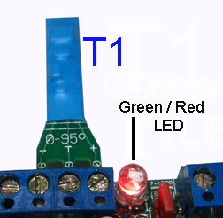
As a test, a 10 mm "low power" LED (we can
provide the LED for free) can be
connected directly to AI5 and GND connections on the right.
Then send the command [Pw A5 0 K5 1 1]
to have one sec On and one sec Off. If the LED does not
flash, just exchange the two connections on Ai5 and GND.
M
Monitor audio [Pw
M?] explains the function.

De
interne microfoon is op positie (52) in de controller kast (niet druken
of draaden binnen duwen daar!). De mikrofoon kan automatisch worden
geactiveerd tijdens een alarm zodat de direct omgeving van de
controller is af te luisteren op afstande via een vaste of mobiel
telefoon. Zie ook op N ** voor meer informatie.
De MIC-functie kan ook worden ingesteld voor auto answer, zodat de controller op een normaal telefoon opgoep aantword.
Voorbeeld:
stuur eerste [Pw M2 s] om de controller automatisch een oproep te
laten beantwoorden naar twee keer ringkelen (de s, optioneel,
laat een statusberichten terug kommen met M2 i.p.v. M0 zichtbaar in de
status). Daarna roep u de controller SIM-kaart nummer als een normale
telefoon met een mobiel of vaste toestel.
De waarden van M zijn geldig van 1 tot 5 maar better 2 of 3 kiezen.
Hang op om het gesprek te beëindigen of annuleer de functie door [Pw
M0] of [Pw M9] te sturen. De MIC zal zichzelf uitschakelen op de vole
uur zo op MM = 59+ 1 van HH:MM. [Pw s] of [Pw m] zaal de werkelijke en aktueel configuratie tonen.
M ingesteld op 9, [Pw M9] Maakt de controller een Status Message terugsturen wanneer hij word gebeld op zijn SIM nummer. De
bericht is verzonden naar het eerste nummer in de lijst op N1 na twee
ringen en de oproep kan worden beëindigd als de derde ring wordt
gehoord.
Bericht [0000 !NummerTeBellen]
aan de controller sturen zal het dit "NumberToBeCalled" draaien met
open mikro waar men zal kunnen luisteren. Gewoon ophangen, een tijdje
of MM 59+1 wachten beindeert de oproep. [0000 !N8] maak de nummer op
positie N8 in de nunner lijst draaien. (Zie bij!)
The internal microphone at
position (52)
of the controller box
(do not push anything in there!) can
automatically be activated during an
alarm so that the controller can make a voice (any fixed or
mobile) phone call by itself to the outside. The MIC function
can also be setup for auto answer, so that the controller
replies on normal phone call. Review also
N at
** for more infos.
For example, first send the [Pw M2 s]
to make the controller auto answer a call (the s, optional, will return
a status message and should be visible as M2 in
the status).
After that, dial the controller's
SIM card number like a normal phone
and you will be able to hear around after 2 rings.
Values of M are
valid from 1 to 5, but rather choose 2 or 3. Hang up to end
the call, recall or clear the function by [Pw M0] [Pw M9]. The MIC will
deactivate itself at HH:59 +1 (so each new hours). [Pw s] or [Pw m] will show the actual
configuration.
M set to 9, [Pw M9],
makes the controller send back a Status short message when
called. This message is sent to the first number in the list
(position N1) after two rings. To get the status
message, when M9, just normally (voice) call the controller
SIM number. The call can be terminated when the third ring
is heard.
A call request to the controller is also possible by command
! and so if we send
[0000 !NumberToBeCalled],
the controller will then dial the "NumberToBeCalled" and so
make a phone call to any phone with open mic. Just hang up
to complete or the controller will do so itself after a
certain time. [0000 !N8] could do
the same with the number at position N8 in the list. (see at !)
T
Temperature alert and
setup for
T1 and T2. list
The thermometer function can automatically send
an alert when the temperature falls
below or above the programmed edges < and >. These edges,
thresholds or limits, as we prefere to call them, are
programmed by the command [Pw T1 2.2
37.5] for example. The alert will be sent by default to N1 (changeable), but a second alert number could be
programmed by [Pw T1N 13] for
example, which makes send the alert to the number written at
position
N13 in the list of
numbers.
As seen at J,
we use function JTn
when an Output needs to be switched if the temperature
exceeds programmed thresholds. So
Junction JT1 kan worden ingesteld op een automatische en eenvoudige verwarmingscontrole
te realiseren zonder temperatuurswaarschuwing met behulp van de T1 thermometer,
(zie JT).
De thermometerfunctie kan u automatisch een waarschuwing sturen bij het
overschrijden van lagere of hogere geprogrammeerde grenswaarden. Om de controller
automatisch een waarschuwing laten sturen als de temperatuur onder 18,4 of boven 21,8
graden Celsius komt, stuur commando [Pw T 18.4 21.8] naar de controller.
Een SMS wordt gestuurd naar het eerste nummer in de lijst. Een nieuwe
waarschuwing zal opnieuw worden verzonden als de temperatuur wederom
binnen het bereik <T> komt en opnieuw de grenswaarde T < of > overschrijdt. Geen
overeenkomstige Temperatuurwaarschuwing worden verzonden indien een of beide grenzen op 0 geprogrammeerd zijn.

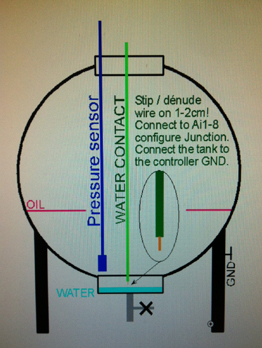 As
already seen, all Ai1 - Ai8 inputs can be used as flooding detector,
overflow and water leakage. An input connected to a simple wire,
striped on fews cm, making contact with GND via the water can force
send a message and operate any pump or other if wanted. Do not forget
to connect the metal mass of the tank to the controller GND or use
another wire connected to GND and mounted at some cm of the sensor
wire.
As
already seen, all Ai1 - Ai8 inputs can be used as flooding detector,
overflow and water leakage. An input connected to a simple wire,
striped on fews cm, making contact with GND via the water can force
send a message and operate any pump or other if wanted. Do not forget
to connect the metal mass of the tank to the controller GND or use
another wire connected to GND and mounted at some cm of the sensor
wire.  SMS Status s or ss
show RST, R0T, 0ST or any combination of it
by absence or presence on R=L1,
S=L2 and T=L3 inputs. Please use the
command [0000 ac+] if the line AC=1 RST
is not yet at the status.
SMS Status s or ss
show RST, R0T, 0ST or any combination of it
by absence or presence on R=L1,
S=L2 and T=L3 inputs. Please use the
command [0000 ac+] if the line AC=1 RST
is not yet at the status. 