GSM
ALARM and REMOTE CONTROL (view schematic at bottom)
SMS CONTROLLER GX8 User manual
V8.x-11 - V1.1.13 Francais
NL
Just insert your SIM card in the SIM card holder, connect the antenna
and plug the delivered power supply adapter into the main power. You
are then
ready to check and get familiar with the functionality before
definitive installation. If any, remove the SIM card pin code with
your own mobile phone before insertion. A prepaid card is also well
suitable.
Send SMS command [0000 ?] to
the controller with your mobile and you
receive back an SMS with the
list of the supported basic functions. Send [0000 ??] for a list of the
extended supported functions. All [commands] are sent as SMS to the
controller.
The following is the whole User Manual! Don't be pushed away by
the huge amount of information, because only the basic functions are
needed for a common GSM Alarm and Remote Control usage.
Don't loos the time to read
more if you only want to remotly switch an output ON Off. Just
connect it to O1 and send SMS [0000 o1
on] or [0000 o1 off] to
the controller.That is all it take and will be same for O2 and O3.
However, the
extended functions were made in a way that one should be able to easily
use them on any installation, even without technical expertise but only
an attentive reading.
Nothing really needs to be memorized, because SMS-help is available for
each supported function. For example, command [Pw O?] sent to the
controller, will send you back a memo SMS telling you what you can do
with
the Outputs. This for each supported function; send the Pw followed
with the function
letter with a question mark ?. ex: [0000 N?]
Basic
Function listing.
(in order of functionality)
? Show this list
in replied short
message. [Pw ?]
S Reply with
Status-SMS.
[Pw S]
A Alarm
Inputs.
[Pw A?]
Ad Display Alarm
Delays. AnA Force
Alarm. [Pw Ad]
N Alarms,
Alerts and warnings numbers list. [Pw N?]
Nd Show numbers
programmed in numbers list. [Pw Nd]
O Outputs O1
, O2 and O3.
[Pw O?]
E Change/edit
Inputs and Outputs names.
[Pw E?]
M Monitor,
for audio.
[Pw M?]
P
Password (default 0000).
[Pw P?]
F Factory
parameters restore.
[Pw F?]
H H:M setting
for time related functions.
[Pw H?]
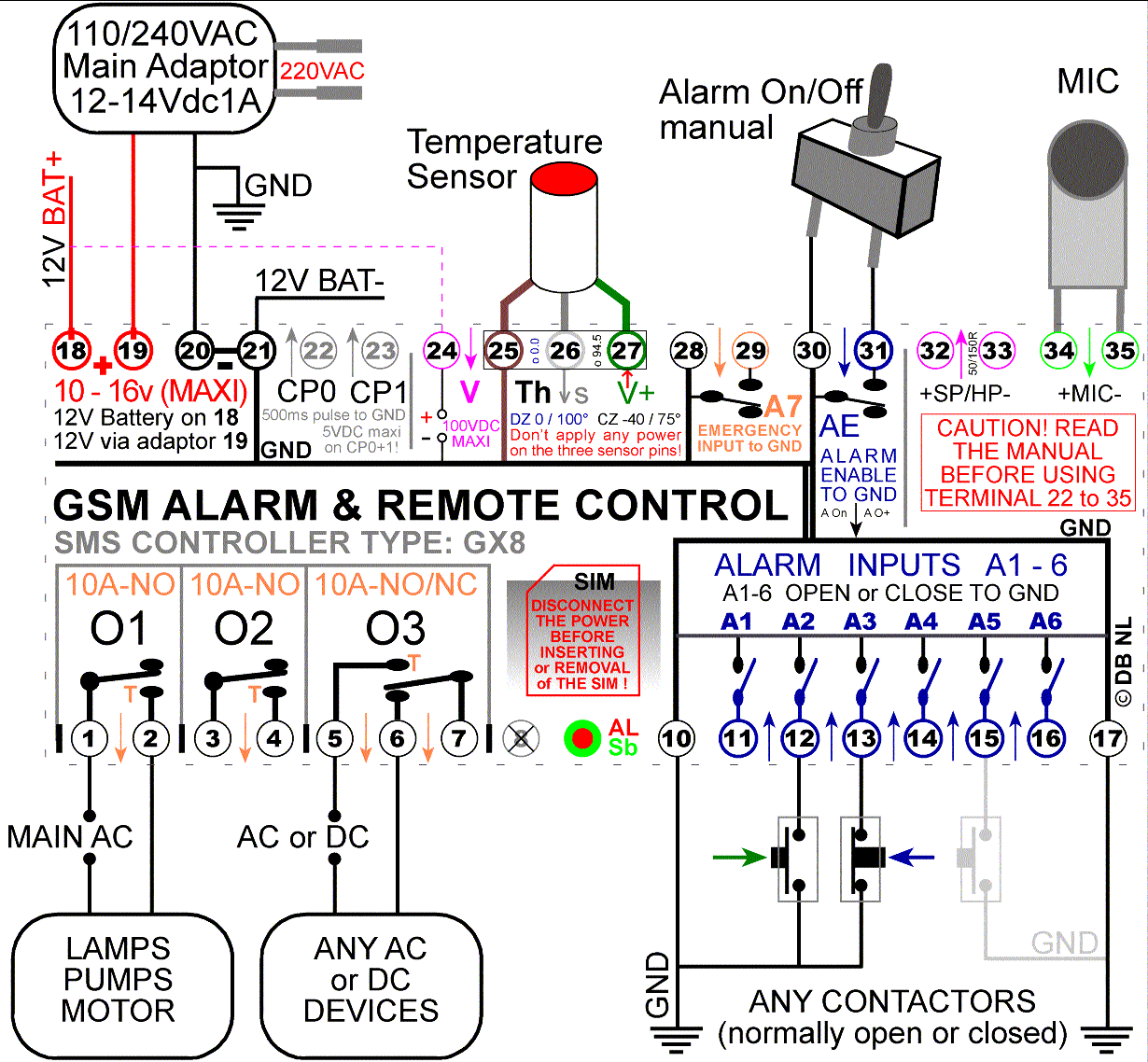
Connection
Scheme example
Advanced
Function listing.
?? Show this list
in replied short message.
[Pw ??]
D Dial to n
numbers for alarm and SOS.
[Pw D?]
I Interval
timing on Output O3.
[Pw I?]
J Junction
Voltm. to O1, Temp, to
O2,,, [Pw J?]
CP For short
Connector Pulse on C1 and C2.
[Pw CP?]
T
Temperature alarm and Thermostat control.
[Pw T?]
V Voltage
alarm and control.
[Pw V?]
R Reseau
(Grid) control.
[Pw R?]
PC
Program / Function Thermostatic
Just insert your SIM card in the SIM card holder, connect the antenna
and plug the power supply adapter into the main power. You are then
ready to check and get familiar with the functionality before
definitive installation. If any, remove the SIM card pin code with
your own mobile phone before insertion. A prepaid card is well
suitable. The led will show
the power up and registration to the GSM network and after one half
minute you can send your first SMS command.
The LED show the
radio module initialization and the connection atemps to the GSM
network. You can start sending [commands] after 30s when the led will
flash at 1 second rate, green when standby and red when alarm is on. As
an extra control, the internal small led will show any communication
with the gsm network (when the sim card is working).
The following exemples below shows; commands sent to the
controller as [bold] and
messages sent from the controller to the cell phone in green.
Pw is the Password that is 0000 until changed and is the only
case-sensitive command
(Do not include the [] from the examples).
S
General status informations. list
[Pw s] to the controller
will
make it reply with the current
status. The reply is sent to any mobile number sending the request.
Status request will be sent to number N1 in case the calling number is
not recognized.
O1 OFF V
Output
1, J1 or V if junction >0 (See Junctions).
O2
ON 500 T
(remaining time On) J2/(T) if JT , Ta ,
Tn See J and Th.
O3
ON
(or OFF) Time left
on
(A) (JH) See JA and JH.
A0-7:
01101100 Level
High, Low. A0 manual enable, A1-6 Inputs, A7 input.
V=24.6
<23.1 >29.5 Voltage
on
input T24, SMS if <23.1 and >29.5)
T=18.2
<2.5 >0 Temperature,
SMS to N1 if < 2.5°, no SMS if 0.
13:45 A=On
Controller
clock time. Alarm On, Off or only O+.
AC=Yes
M0/9
Yes/No Grid Power.
Mic On >0 (M2) M9=Status on call.
One or more status messages can also automatically be received every
day, see H? therefore.
A
Alarm Inputs.
Ad Display Alarm Delays.
AnA Force Alarm.
Up to six
alarm inputs can be connected. The sensor (or group of sensors) can be
any switch or magnet contacts directly connected to the controller. Any
device, like motion detectors or fire alarm sensors with a potential
free output that can make or break a circuit (like a switch does), can
be used. Any change on Inputs A1 to A7 will trigger the alarm and the
emission of Alarm SMS after the corresponding Input Delay.
The Alarm function is standby when A=Off and is in watch when A=On or
A=O+ as shown in the status-SMS.
Alarm can be switched On manually with Input AE (A0) T31 to GND or Off
when T31 is left open. Command [Pw
A On] or [Pw A Off] can
be
mixed with the manual setting. Command [Pw
A O+] prevents the
alarm to be set off with the manual switch.
An Alarm SMS will look
like; One valid number
(N1) or more are
required and need to be programmed in number list.
ALARM! A1
(A1 or assigned name)
see E
A1=Low(0) or
High(1) Trigger!
Delayed SSSS
sec. Corresponding input delay. See Ad
A0-7: 10111111
The Level of the 7
alarm Inputs.
Pw S,
Ad?, J?, M?
Suggested commands.
Alarm SMS
count. Default 5. See parameter D.
Alarm SMS are sent after each other up to parameter Dial, see [Pw D?].
Valid numbers are needed in the number list N1 to Nn see [Pw N?]. When
alarm occurs
and that alarm SMSs are sent, the action (also Ja>1) can be stopped
with [Pw] or any command to
the controller.
An Alarm input must stay low(connected to GND) or high(disconnected
from GND) for minimal 25ms in order to trigger the SMS alarm sequence.
Ad
Display Alarm Delays. list
Each alarm input A0 to 7 can have a delay assigned to it. This is the
delay before an alarm SMS will be sent after corresponding input level
change. So [Pw A1 20 A2 500]
will assign input 1 delay to 20 and A2 to
500 seconds. Delay input A0 sets the delay in seconds to get out before
the alarm goes from Off(standby) to On(watch) when alarm is activated
with input 0 (T31) to GND. Delay can be from 0 (no delay) up to several
minutes ex: [Pw A0 180] will
set the exit delay to 3min. No EXIT Delay
is accounted when the Alarm is turned On via SMS. It then immediately
goes to On (watch).
Command [Pw Ad] will make SMS you the actual input delays.
0=30
EXIT! 30s before alarm
goes on watch.
1=2 A1 A1
to A7 can have
other names. See E
2=1 A2 Change
on input send ONE Alarm SMS to N1 in list.
3=8 A3 Delay
is 8 sec so SMS are sent after 8 Sec if A=On.
4=0 A4 Input
is disabled
(No alarm) Timing delay = 0
5=32 A5 Send
Alarm SMSs after
32s.
See D?
6=60 A6 This
delay is
actually programmed to 1 minute.
7=1 A7 Set
it to 1 or 2 when
used for SOS alarm.
23:58 A=Off Controller
time.
Alarm On, O+ or Off.
AC=No M0/9 Grid Off, no
Mic off (0),
Status on call(9).
Two last lines (also in the status SMS) are only added if all fit in a
standard single SMS that normally has up to 160 Characters. So edit
short names for the input when wanted...
Any delay at 0 will disable the corresponding alarm input. [Pw A?] will
reply with the Alarm function infos. [Pw
Ad] shows the alarm delay and
[Pw s] the input levels and
actual alarm setting.
Eventually, A1 to A6 can make send only one SMS alarm N1 to N6
programmed numbers on alarm event
if corresponding A1 to A6 delay is set to 1. So program the delays
superior to 1, from
2s to any minutes otherwise only one SMS will be sent out to the
corresponding number (if programmed) (see N).
The SOS Emergency function can alarm you via SMS. Input A7 (T29) is an
emergency input that will always send an emergency SMS no matter if the
controller is in alarm-, watch- or standby mode. A simple push or
any on/off switch can be connected to this emergency input. Better give
the
SOS Alarm input A7 a short delay 1 for a push switch or 2 for a
bi-stable switch. N1 should be programmed or SOS will be send to last
received number if any or next numbers in list.
In case of an Emergency alarm event that make Input A7 change level
(T29 to GND or
released), an EMERGENCY ALARM is SMS to N1 and any other programmed
numbers (see also programming numbers N and D).
SOS SMS can be edited to your own needs. like; “Urgent! call 323123456
immediatly!” See E (sos) to Edit the SOS.
AnA
Force Alarm. list
AnA: Forcing an Alarm event for test purpose.
When the alarm is on watch, A=On or A=O+, command [Pw AnA] to the
controller will simulate alarm input An change and will reply with an
Alarm
SMS to number N1. n can be 1 to 7.
Remember that any level change (suddenly GND to disconnected or the
opposit will trigger the alarm after the
corresponding input delay time (if not Zero) unless the alarm is put in
standby mode with either AE(A0) to High level (disconnected from GND)
or a [Pw A Off] SMS to the
controller.
This gives a real Alarm test for input A1 to A7, the 6 alarm
inputs and A7 the SOS input.
N
Programming the numbers (up to 40) where to send SMS for SOS and
ALARM.
Command [Pw N?] will reply with
an SMS that will remind you what you
can do to program the numbers.
At least one (mobile) number needs to be programmed at position 1. In
many cases, number n1 will be the one where the controller will send an
SMS. To add a number to the list at position x, just send command [Pw
Nx NUMBER] ex: [0000 n1 06554422]
Upto 40 numbers can be programmed.
[Pw N1 0655520 N3 +3120555 N8
+33123456 N5 06xxxx Nd] programs several
numbers in one time. Nd (optional) makes reply with the numbers list.
No blanks inside the numbers! Numbers can be anywhere in the list but
numbers at lower positions are called first from N1.
* Alerts are
messages sent when the Low/High Bottom/Top
configured edges are exceeded. They are simply setup with the
function name followed by the Low and High parameters. So for example
for V to 11 and 14 volt, [0000 V1 11
14] See also T and R.
Warning
message
are optionally send by
the Junctions with parameter JS and the
< > edge parameters. They
will notify, when wanted, of
an junction action on the Outputs.
The Alarm
function, when activated, will send an Alarm messages.
So except the status and info's and configuration
messages received on request, we can get three kind of messages from
the controller;
Alerts, Warnings,
and Alarms.
Nd
listing the numbers. list
[Pw Nd] will
send back an SMS displaying the numbers
found in the list from position 1 until full SMS of 160 charatersl.
1 061234567
2 +32541234
6 +33424555
10 00491245
20 Anyto15chrs
22 06123456
26 Memo txt (optional)
30 %Atcode (optional)
Command [Pw nd 12] will start
listing from position 12, or above if
none there. Programming a number at any position will
overwrite a number already there. To definitively delete (=kill) a
number from the list, N6 for example, just send SMS command [Pw
n6k].
Any short memo-text (15 characters maxi) can be written at any unused
number position and will also be listed with [Pw
nd]. Ex: [Pw n20 Any to 15chrs]
will write "Any to 15chrs" at position
20. Just then do not
use any digit 0-9 or + at first line position!
The numbers memory can also be used to configure the GSM engine at
start up. Text written there will not be overwritten by a number when
the line beginning with character %. So any "%ATcommand" can be written
there,
for example; [Pw n30 %Atcode].
Use this function (best do not use it)
with caution because
any wrong or inadequate AT command could stuck the controller GSM
radio (ask us).
O
Outputs O1 , O2 and o3. Command [Pw o?] gives details on
the output function.
The 3 power outputs let you remotely drive any machine or high power
equipment with a simple SMS command . Output 1 and 2 are (On/Off) and
Output 3 (On/Off/On). Up to
10A 250VAC 2500W can be switched*. Be
careful when connecting high voltage to the output!
Timing up to 65500 seconds can be added to the command. No timing
(just: On) will make the output simply switch On until an Off-command
arrives.
To switch an Output On or Off, send command [Pw O1 on] or [Pw O2
off] Multiple commands are supported in the same SMS
command to
the controller; [Pw o2 on 55 o3 off O1
on 5 s]. An optional trailling s
will force the controller to send back an SMS that
will show the new outputs status including timings. This only if the
command was successful and correctly spelled.
To switch an output On for 3 min send command [Pw O1 on 180] for 1 hour
[Pw O2 3600] , [Pw O1 on 32 O2 on 500 o3 off s]
Output can be given a meaningful name such as Pump, Light, Motor... You
can Edit the Output 1 to 3 as you like.
So if Output 1 O1 is Edited to Pump, command [Pw Pump on 600 s] will
switch the pump for 10min. (See E , editing the In and Outputs for
details).
Status SMS will then show;
PUMP ON 600
O2 OFF
O3 OFF
etc...
* DANGER! Great care is
recommended when blindly switching any
machines or devices remotely. Furthermore, the switching order, that
normally arrive in a few secondes, could
arrive delayed at the controller due to a GSM network overload or any
other
possible or unexpected reasons. Therefore and in general, really know
what you do and always disconnect the controller outputs and power
before any work or maintenance on the connected devices.
E
EA Editing the Alarm Inputs A0-A7 list
A single SMS and 15 characters can be used to rename Alarm Inputs A0 to
A6. Avoid (possible) blank characters in the name to make it easy to
spell. Choose short and meaningful names.
To Edit Input A2 into Backdoor, send command [Pw EA2 Backdoor] to the
controller. An alarm SMS on A2 will send you;
ALARM! BACKDOOR
Input A2 = Low(0) Level.....
To Edit input A3 to Garage, send [Pw
EA3 Garage] to the controller.
Alarm on A3 will send you; ALARM! GARAGE.......
To Edit A4 to Freezer Alarm, send command [Pw EA4 Freezer Alarm!] to
the controller.
[Pw EA0 attention] will replace
ALARM! with ATTENTION or any wanted word
(15 chrs maxi) in the alarm messages.
The SOS message can be edited too. Up to 60 characters [Pw EA7
Problems! call me immediately at 065654254]
Actual names are listed in the delay timing SMS. So
[Pw ad] will show:
0=180
EXIT!
1=20
A1
2=500
BACKDOOR
3=4
GARAGE
4=8
FREEZER ALARM!
5=32
A5
6=64
A6
7=1
Problems!
call...
Use A7A to view full SOS message.
(sos): If A7 delay is 1 or 2, one SOS message up to
60 Chr is sent by any A7 input change. However, there is a way to make
send two different messages of 30 chrs maxi only for each A7 level
change. Therefore set A7 delay to 3, edit the first low level message
with [Pw EA7 String up to 30 chrs for
Low!] and the second high level
with [Pw EA9 Up to 30 chrs for High
level!]
If A7=3, the first message is sent to the first mobile number N1 in
list and the second to second number to N2.
To again rename an Input to an OtherName should be used and not the
aliased name. So [Pw EA3 OtherName]
will replace GARAGE by
OtherName.
EO
Editing Outputs
O1-O3 names. list
To give O1 the name PUMP, send SMS command [Pw EO1 pump] to the
controller. To Edit Output O2 to LIGHT, send command [Pw EO2 light] and
for O3 [Pw EO3 NewName]
Actual Output names are listed in the status SMS so [Pw s] to the
controller will show the output names.
PUMP OFF
LIGHT ON 320
NewName OFF
etc........
The Alias should be used to command any switching on the outputs. So
choose short, meaningful and easy-to-remember output names. To switch
on the pump for 15 minutes and the light for 1H, send command [Pw Pump
on 900 Light on 3600]
To rename again an Output to an OtherName On should be used and not the
aliased name. So [Pw Eo1 OtherName]
will replace PUMP by OtherName.
M
Monitor, for audio. [Pw m?] Send Pw M?
explains about the function [Pw s] shows the M setting.
A Microphone (delivered) can be connected to terminals 34 (negative,
black), 35 (positive, red). So if you put some device On remotely,
send [Pw M3] to the controller.
After this you can normally voice-call
the
controller and after 3 rings you will be able to listen. Values 1 to 5
are
valid but rather use 2 or 3.
Just hang up to terminate the call, call another time or disable the
monitoring by sending [Pw M0]
or [Pw M9] when finished
because the
SIM could be called from anywhere by anyone else. A small speaker 16 to
50 Ohm 0.5W can
also be plugged at T32 T33 for duplex audio. Don’t install the speaker
next to the Microphone and install the antenna
as far as possible from the MIC.
M set to 9, [Pw M9] makes the
controller send back a Status short
message when
called.
Message is sent to the first number in the list at position 1 after two
rings. To get the status message, when M9, just
normally (voice) call the controller SIM number. The call can be
terminated when the third ring is heard.
P
Password (default 0000).
Changing the password.
[Pw P?] says how. list
The begin Password (Pw) is 0000. To change it, send SMS command [OldPw
P(NewPW)]
To change it to ABC send [0000 P(ABC)]
and to change it again for 1+2=3
send [ABC
P(1+2=3)]
The Password is 3 to 7 characters or digits maxi and case sensitive
with no blank
in it. Keep it as short as you desire to make things fast and easy. If
the Pw is lost or forgotten, disconnect the controller power, connect
C0 to C1 and power-up the controller again. The default settings are
then restored, see (F?), and the Password will be 0000 again. Don't
forget to disconnect C0 from C1 after more than 1mn. See informations
by
sending [Pw P?] before
changing the Password and be sure what to do. CO is Terminal 22 and C1
T23.
F
Factory parameters restore. [Pw f?] to the
controller replies the details function. list
In case of a major problem, sending [Pw
FSR] to the controller will
force restoring the controller and the Parameters to the default
factory settings. Wait 30 seconds and use Password 0000 (4 x zero)
after a Fsr command. Then start to program the parameters to the
wanted values. Number list and possibly edited inputs and outputs names
need to be checked as well, see N? Ad and E?.
[Pw Fz] only
initializes/restarts the built-in radio module (the one
that connects to the GSM network), password and parameters
remains the same. This action has the same effect (but from a distance)
as removing and re-establishing the controller power.
Use Fz if there is some doubt about the system behaviour. The F?
function shows the init and restore count, version and GSM auto
restore count principally due to loss of connection.
H
H:M setting for time related functions.
[Pw h?] will reply with the H , H- , H+ and Hc actual settings.
To set the controller soft and hardware time clock at 14:49 use [Pw H
14:49]
This software clock, is also needed for night and day parameters Hn and
Hd of the thermostatic function, Junction JH and function Hs.
The clock also tells about unexpected system resets (watchdog) because
it always restarts at zero when the controller is powered On or by the
FSR or
Fz
command.
By default and as control, a Status SMS is sent to number N1 5mn after
power on or initialize if no command is
received by the controller before this laps. The time shown in the
status is then 0:5. After that (from V8.4-11 (use [Pw F?] to know)), the
software clock will synchronize with the hardware real time clok if
Hc=0 and if no power interruption have occured, set all to the right
time. (the hardware real time clock is both feeded from bat or adaptor
power).
The clock can be adjusted before or after any other command. Like here
with [Pw H 12 14 O1 Off s]
Hc is a clock correction parameter that can be used (if not 0) to tune
the clock the software clock. If you think the clock is too fast with
3s a day send [Pw
Hc -3] and if too slow down by 4 set it to 4 with command [Pw Hc 4]. [Pw Hc
0] will force use the hardware RTC clock that do not needs any
correction.
[Pw Hs 12:15 h?] Will force a
Status SMS to N1, each
day, at 12:15 and command [Code Hs 0:0] will make it stop. This will give a good control of the system. See also
[Pw *?] when more status
messages are required than one a day.
Special functions
&
Parameters: These
functions/Parameters are available but are
not really
needed for normal basic Alarm- and Remote Control use. So you
could ignore them if you are not using the following functions.
Fast configuration of one or several controllers can be done using our free
Windows PC
program. Testing will be very easy, because SMS and PC
traffic/commands
can be
used simultaneously. Download, save, unzip
and install (optional cable is required)...
The PC can do all the same that can be done with SMS, but simply
with a few
mouse
clicks from the command list. As before, also a firmware update can be
loaded
into the controller via the program. Any added custom functions are
also
available on request.
Click
to go back to the functions
list at top.
D
Dial to n numbers for alarm and SOS.
[Pw d?] Shows the details and the actual
values. list
Programming how many numbers will receive the message for SOS and
ALARM. Parameter Dial tells to how many numbers in list the SMS is
sent. No SOS or Alarm SMS will be sent if corresponding or both
parameters have value 0.
Command [Pw D 2 5 d?] will make
the controller send SOS-SMS to the 2
first numbers found in the numbers list and Alarm-SMS to the 5 first
numbers found in the same number
list. Numbers found at lower position will be served first. (See N
above to programne the numbers)
I
Interval timing on O3
[Pw
I?] gives details on the function. [Pw s] show the Interval
values. list
Output o3 can be used as an Interval timer up to 65500 seconds
(>18H).
[Pw I3 40 3600] will switch on
Output O3 for 40 seconds, wait 3600s
(1H) and switch it on again for 40s. Again and again until command [Pw
I3 0] or others Interval values are sent to the controller.
Interval
output
3 is on terminals 5 and 6 or 7. The Interval function works in both
alarm modes, On or Off. The Interval timer swicth O3 on a
programmed delay while JH below, switch on programmed clock time.
This function is NOT
available on all controller! SMS command [Pw I?] will
reply info's if supported.
J
Junctions functions J1
A1-O1, J2 A2-O2, JV-O1, JT-O2, JH, JA.
[Pw j?] Shows the junctions
Outputs 1 and 2, can be automatically
driven by Inputs 1 and 2 with a Junction function, Timed or Level. The
Junction works disgarding of the present alarm mode On, O+ or Off.
J1 Timed Junction
between A1 Input and Output O1 can be made by sending
command [Pw J1 60]
A change from High(disconnected) to Low(to GND) on alarm Input A1 will
immediatly (No delay) switch Output O1 ON and
switch it Off
after 1 minute. The Input A1 needs to be High again before O1 can be
switched again. Timing can be from 2 to 65500s
(>18H). [Code
J1 0] remove the Jonction A1-O1.
- Level Junction A1 Input and O1 Output can be made by sending command
[Pw J1 1]
A
change to Low Level on alarm Input A1 will switch Output O1 On, after
delay A1, and will
switch it Off only when Input A1 goes back to level High(1)
(=disconnected)
again. So to be clear, when delay A1 is set to 10 seconds [Pw A1 10
Ad?], the input must keep low level for 10 seconds before the
output is
set On. [Pw J1 0] will
remove the
Junction A1-O1. JV below also using O1 disables J1 (Use J2 if needed).
J2 All the same for J2
that
virtually connects A2 to O2. J1
and/or J2 >0 disable the corresponding alarm input. However,
parameter JS can force a status SMS when O1, O2 is switched with
J1 or J2. See therfore JS below. JT below also using O2 disables J2
(Use J1 if needed).
[Pw JV 1] to the controller
will enable a Junction between the
voltmeter (Terminal 24) and output O1 (T1+2).
If voltage edges are programmed to <11.1 >14 and
the voltage goes below 11.1 output O1 will be automatically switched
On. The Output, O1 will then switch Off when the voltage becomes
superior to 14 volt.
This Junction can give a simple but effective charge
control. Command [Pw JV 0]
remove the Junction and re-enables the low < and high > voltage
warning messages. JV >0
disables the J1 function and so the simple V < > warning
messages, but an Alert message can be sent with JS (here below).
From version V1.1.13 (delivered from 2013) Bottom and Top Alert message can be programmed
with the parameters VB and VT. This independently from the switching
level of JV (defined by V < >). A good advise is to use them for
Alert Mini/Maxi level may the voltage still exceed the settings V <
>.
Example: For a charge
control with JV (on O1) from 11.5 to 14 volt with a battery charger,
one can programme Vb à 11 et Vt à 14.5.
Command [Pw V 11.5 14
JV 1 JB 11 JT 14.5] to
the controller can do it at once. An Alert Vb or VT will then notify a
charger failure or simply a power fail on the charger (like AC=NO).
Always check that the parameters are well programmed into the
controller within this case, command S ou J? et
V?
[Pw JT 1] to the controller
will enable the junction with the
Thermometer sensor (T25,26,27) and output O2, (T3+4).
When the Temperature edges are
programmed to <18.5 >19.5 and that the temperature goes below
18.5 Output O2 will automatically be switched On. Output O2 will switch
Off when the temperature becomes superior to 19.5°.
This Junction gives a simple thermostatic control (See at
bottom for an extended thermostatic function). No
SMS temperature alert is sent out if JT is >0. Removing the
Junction JT with
command [Pw JT 0] to the
controller re-enables the normal simple low and high
temperature warning messages. JT
>0 disables the J2 function.
From version V1.1.13 (delivered from 2013) Bottom and Top
Alert message can be programmed with the parameters TB and TT. This
independently from the switching level of JT (defined by T < >).
A good advise is to use them for Alert Mini/Maxi level may the voltage
still exceed the settings T < >.
Example: For a heater
control with JT (on O2) from 19 to 20.5 degrees with a heater,
one can programme TB to 11 et TT to 25 or more.
Command [Pw V 19 20.5
JV 1 JB 11 JT 25]
to the controller can do it at once. An Alert Vb or VT will then notify
a heater failure or simply a power fail (like AC=NO) or tank empty.
Always check that the parameters are well programmed into the
controller within this case, command S ou J? et T?
Command [Pw JH 1] to the
controller will make O3 swith On and Off with
parameters Hn and Hd. Hn switch O3 on and Hd will switch Off. These two
parameters are also used for the extended thermostatic function
(see below).
Hy and Hz gives a second On Off swith time for JH if set to 2. So
command [Pw JH 2 Hy 10:55 Hz 15 15 H?]
will make O3 switch On at 10H55
and switch Off at 15H15. H? show the parameters.
JH to 3 use all 4 parameters Hn, Hd, Hy and Hz. So command [Pw JH 3 Hn
0 15 Hd 8 30 Hy 10 55 Hz 15 15 H?] can do. Any of the Jh
Junction can
be removed by resetting corresponding parameter to 0.
[Pw JA 1] Will make output O3
automatically switch On and Off
together with the Alarm mode. So when
the alarm goes to A On or A O+ Output 3 will also go On. It will go
again when the alarm mode also go Off. This can be required if a
device needs to be automatically activated according to the alarm
mode, a second alarm, camera, lamp or other (JA do not activate Js 16.
See Js just below).
JA > 1 will switch O3 for JA value (2-250 seconds) on alarm event.
So a sirene, light or else can be switched On. [Pw JA 0]
will remove the junction JA. JA >1 does not activate O3 when
corresponding input delay A1 to A6 is set to 0 or 1, that SMS only to 1
number (see Ad).
JS
can force a Status SMS to N1 when
Junctions J1, J2,
JV, JT are active.
1 will make send a
Status SMS
when J1 makes switch
output O1. [
Pw Js 1]
2 will make send a
Status SMS
when J2
makes switch
output O2. [
Pw Js 2]
4 will make send a Status SMS when JV makes switch
output O1. [
Pw Js 4]
4 removed from V1.1.13 (2013). See the more
effective
parameters Bottom/Top at V?
8 will make send a Status SMS when JT makes switch
output O2. [
Pw Js 8]
8 removed from V1.1.13 (2013). See the more
effective
parameters Bottom/Top at T?
16 will make send a
Status SMS
to confirm O3 switch Off. [
Pw Js 16]
Any mix is possible, so for J2 together with JV, add 2+4 and send [
Pw
Js 6 j?].
Function JS needs a number to be programmed at
position
N1 of the number list.
Only use very large delays for J1 and J2 in timed mode in
combination
with JS and be aware that a of SMS could be sent out with fast
repetitive switching of the outputs via Junctions!
These Junctions are only soft and not physical ones but they will act
the same. Each or some enabled junctions can be reset to 0 by command
[Pw
Jn 0] to
the controller or all at once with [Pw
J1 0 J2 0 Jv 0 jt 0 Jh 0 Ja 0 Js
0 J?]
CP
for short Connector Pulse on C1 and C2.
[Pw cp?] Will show the functionality. list
As requested, from V1.1.13 (delivered from 2013) (Pw
F? will show the version number) Cp0
and Cp1 give a High level 500ms pulse of 4.7 Volt or have GND level
(about 5mA both ways). The command is now simplified to [Pw Cp0] or [Pw
Cp1]. The two inputs still can make restore Pw to 0000. Ox and
Oy are removed from Version V1.1.13.
Command [Pw CP0 L] to the
controller will reset CP0 (Terminal T22) to
GND
for 500ms (read ½ second) before going High level again. Command
[Pw CP1 L] to the controller
will do the same with CP1 on Terminal T23.
Command [Pw CPX L] will set off
optional output CX and [Pw CPX H]
will
set it to High level. OX needs to be specially wired (by a specialist
to prevent any damage) before use!
Low level voltage on CP0 and CP1 is about 0V(GND) and High level is 4
Volt.
Absolutely don’t apply any voltage on CP0 , CP1 or OX or the controller
will be damaged (no garanty for this). Inputs CP0 and CP1 are also used
to restore the password when lost (See P?).
T
Temperature alert and control.
[Pw t?] [Pw s] list
The thermometer function can automatically send you a Warning when
exceeding lower or higher programmed limits.
To make the controller automatically send an alert if the temperature
goes
below 18.4 or above 19.8 degrees Celsius, simply send command [Pw T
18.4 19.8]
to the controller.
Temperature Warning SMS, issued
to the first number in list N1;
Temperature
LOW Limit! = 18.3 (HIGH! if
19.9), sensor temp.
T<
limit = 18.4
Lower programmed
Temperature <
T>
limit = 19.8
Higher
programmed Temperature >
Use Pw
T? or Pw s
Recommended
infos. (See JT)
One SMS is issued to the first number in the list. A new warning will
be
sent again if the Temperature first goes back in range < T > and
exceeds again any limit T < >. No corresponding Temperature
warning is sent
when if one (or both) limit is programmed to 0.
The standard delivered Thermometer sensor reads 0 to 100 degrees
Celsius. The optional sensor can read from -40° to 80°.
This standard sensor will be plugged on the controller top at terminal
T25, 26 and 27.
For the optional wired sensor (the standard sensor can also carefully
be wired), connect the three conductor wires with
Brown on
T25, White on T26 and Green on Terminal 27. (THIS wihtout any error!)
The temperature sensor can be offset with a negative or positive value
(default is 0 bc its allready very precis). So if one thinks that the
sensor shows 0.6° too low,
send command [Pw To 0.6]. If
0.2° too high (because pugged above the controller), just trim it
with
command [Pw To -0.2] The offset
is
also shown with command [Pw T?].
Junction JT can be setup to give an automatic and simple heating
control without SMS
temperartue warning, (see JT). But for an extended heater function, see
below the details explained at the “Thermostatic
control function”.
From version V1.1.13 (delivered from 2013) a Bottom and Top
Alert messages can be programmed with the parameters TB and TT.
So when
programmed, the normal alert messages defined by T < > are not
send any more but TB and/or TT. A good advise is to use TB and TT for
Alert Mini/Maxi, may the
temperature still exceed the settings T < > when using JT or the
thermostatic
function.
V
Voltage alert and control.
[Pw v?] list
The voltmeter function can automatically send you an Warning when
exceeding lower or higher programmed limits.
To read the actual voltmeter value, send command [Pw s] The voltage
will be sent back together with other parameters in the same SMS. To
make it automatically send an warning if the voltage goes below 10.8 or
above 28.5V send command [Pw V 10.8
28.5]
Voltage Warning SMS, issued to
the first number in list n1, looks like;
VOLTAGE
LOW Limit! = 23.1 (HIGH! if
28.6) Voltage at T24
V< limit = 10.8
Lower programmed
voltage <
V> limit = 28.5
Higher
programmed voltage >
Use Pw V? or Pw s
Recommended infos.
(See JV)
Voltage from 0 to 80V Direct Current can be read and programmed to the
limit edges.
No warning will be sent when the corresponding low/high limit is
programmed to 0. A
new warning will be sent again if the Voltage first goes in range <
V
> and exceeds again a limit V < >.
Take care when connecting high tension to the voltmeter input T24. Any
mistake could damage the controller at your risk if this High tension
wire is
wrongly connected!
The Voltmeter can be offset with a negative or positive value (default
0). So if one thinks that the sensor shows 0.5V too low, send command
[Pw Vo
0.5]. If 1V too high, just send command [Pw Vo -1.0] The offset value
is
also shown by [Pw V?].
The V
function can be used to monitor a batterie that could supply the
controller. To get the battery voltage in the status SMS, simply
connect the battery positive (normally connected to T19) to terminal
T24 which is the Voltameter input. For a simple
automated voltage control (see JV).
As for the Temperature function, an average algorithm makes the Voltage
value slowly de/increase while reading the voltmeter inputs at about
1V/s 1D/s rate. This suppresses definitively any voltage spikes or
disturbances on the sensor connection cables like the one normally
caused by the
GSM radio.
From now delivered version V1.1.13 (delivered from 2013) a Bottom and Top Alert message can be programmed
with the parameters VB and VT. This independently from the switching
level of JV (defined by V < >) when used. A good advise is to use
VB and VT for
Alert Mini/Maxi level may the voltage still exceed the settings V <
> when using JV.
So when programmed and using JV, the normal V < > alert messages
are then not send but VB and/or VT...
R
Reseau (Grid/main power) alert and control (on
T19). [Pw r?] shows infos and settings. list
The controller can be powered in two ways. By the main grid
power via an adaptor 220AC to 12Vdc and eventually a battery (or or
any other power source from 10 to 16Vdc).
The advantage of a double power source is that if the grid fails, the
controller can go on with the batterie supply and will be able to send
a "grid power fail" alert message with the programmable function R.
Never apply the grid power directly on the controller! The 220VAC to
12Vdc adaptor will be connected at terminal T20(negative) and
T19(positive). The 12V battery or other when used, will be connected
at T21(negative) and T18(positive).
When the controller is double powered the R
function can send an alert when power fail to come from the adaptor at
T19. This
gives an easy grid (main power) control.
Command [Pw R-] to the
controller will make send an Alert on
Adaptor Power OFF.
Command [Pw R+] will make send
an Alert sms on
Adaptor Power ON.
To reset the function, send [Pw r0].
Both parameters are then reset and
one or both can be setup again.
Command [Pw R- R+ r?] could
sets both cases, and replies with an info's SMS showing
the (new) actual settings. The Reseau (Grid) alert SMS to number N1
will look like;
AC
Power OFF for >5s! or ON, when Grid
comes again (R+).
See Pw
R? [Pw r?], [Pw s] also shows AC=Yes/No.
For a generator control, the adaptor (we also deliver suitable adaptor)
will be plugged in the generator
high voltage output 100 to 270VAC and supply Terminal T19+ and T20-.
The 12V generator battery will be connected to T18+ and T21-. This way,
an alert can be sent may the
generator high voltage fails or when the engine stop.
For even more reliability, the engine battery can as well be monitored
with the controller Voltemeter at input T24 because the function V can
also
send an alert message if the battery get to low (see V). For a
generator control, any alarm inputs A1-6 can be used for oil and other
control (see A) while outputs O1-3 can start and stop the engine (see
O).
In fact, the controller has enough possibilities for a full generator
set control and no other hardware needs to be added.
The controller power supply will need about 25mA in standby mode (A On
or A Off, with O1-3 output Off) but some times current
pulses up
to 1 Ampère when transmitting. So only adequate power supply
should be
connected. If On,
the 3 output relais take about 20mA each.
The PC
program. Explainations
how to use are in de prog infos files. list
Fast configuration of one or several controllers can be done using our free
Windows PC
program. Testing will be very easy, because SMS and PC
traffic/commands
can be
used simultaneously. Prog
interface Download, save, unzip and install...
The PC can do all the same that can be done with SMS, but simply
with a few
mouse
clicks from the command list. As before, also a firmware update can be
loaded
into the controller via the program. Any added custom functions are
also
available on request. RS232 TTL level (requires our special
interface cable, same as previous controller types).
Thermostatic
function. [Pw T?] or
[Pw h?] will show all the thermostatic settings. list
As seen above, the thermometer function can send you an SMS to show you
the local temperature on demand or automatically and JT can archive a
simple but effective thermostatic regulation. But the following will
give much more
possibilities, because the function can automatically lower the
temperature at night, between two programmable times, and even more
when the controller is in alarm On or O+ mode. Attentive reading will
show that the use of it presents no more difficulty than a normal
advanced thermostat and that here all can be
setup via SMS commands to the controller.
It can be used to automatically and/or remotely control the temperature
of a far away location like workshop, chalet/house, boat and other with
simply a connected electrical or combustible heather via the controller
output O2. Connection to a central
heater installation, mostly gas or fuel, is also easy via the on/off
control input of
the central heater itself.
If enabled, the Thermostat function will switch the heater on via
output O2 (T3-T4 shorted) when the temperature becomes lower than <T
and off (T3-T4 open) when higher than >T. No SMS is then sent out
when the
temperature exceeds the < > edges (or with JT) but only O2 is
switched On or Off.
Reading of the temperature is still available with command [Pw s] to
the
controller, that also shows the actual temperature and the < and
>
parameters, giving the wanted value of the actual selected working mode.
The thermostatic regulation function knows 3 modes;
(d)ay: T
<T >T
Normal day temperature, no time or alarm
restriction.
T = T
(n)ight Tn Hn to
Hd Lower night
temperature. Let's say after 23H15 and before 08:30 (day).
T = T - Tn
(a)larm Ta (if A=On)
Much Lower
temperature when Alarm is On (no one home)
T = T - Ta
If only mode 1 is needed don't read further and just use JT because it
does just the same. In both cases, parameters <T and >T will
have the switching edges with < the lower and > the higher switch
temperature.
To enable the function in night mode, parameter Tn needs any value not
0, mostly lower than <T.
To enable alarm mode, Ta will also need a value, mostly lower than
Tn.
So we send SMS command [Pw T 19.5 20.5
Hn 23:15 Hd 08:30 Tn -5 Ta -15]
to the
controller
1- O2 switch On when T
gets below 19.5° and Off with T higher than 20.5° during
the DAY from 8:30 to 23:15. T=T
2- O2 switch On when T gets below 14.5° and
Off with T higher than 15.5° during the NIGHT from 23:15 to 08:30.
T= T -5°.
3- O2 switch On when T gets below 4.5° and
Off with T higher than 5.5° when Alarm is On or O+. T = T -15
Mode 2 needs parameters Hn and Hd be programmed at the wanted time.
Like [Pw Hn 23 15 Hd 8 00 h?]
where optional trailing H? (or T?) will
return an
SMS showing the parameters configuration.
Normal status message [Pw s]
will show as usual the actual temperature
T but the actual parameters <T and
>T at which the regulation occurs at the moment, day, night en
alarm.
So; <19.5° >20.5° for day,
<14.5° >15.5° for night and <4.5°
>5.5° when alarm is On.
So when <T = 19.5 and >T 20.5 and Ta is set to -15°, <T
and >T will change to <4.5 and >5.5 as soon as the Alarm is
switched On, until A is switch Off manually with A0/AE or via SMS
command [Pw A Off].
Don't chose a too small window; <T >T superior to 0.6
degrees Celsius or more depending on the heater reaction.
Parameter Ta add a substantial gain to the thermostatic function
when the local temperature also needs to be controlled while the Alarm
is On. Like the Tn value in night mode 2, Ta will be added to
the
<T and >T parameter in alarm mode if A=On or O+ and temperature
regulation will be scaled according to Ta. To have an alarm mode
regulation 12° below normal day temperature settings, send
command; [Pw Ta -12]
[Pw H 10:55 T 18.6 19.2 Hn 22:30 Hd
07:45 Tn -3 Ta
-14 T?] is also a valid
command to the controller that setup all at once and will reply showing
the new settings. Note that 1 space
chr is found
between each parameter and value and that if wrongly spelled, no answer
will come back!
Parameters Hn and Hd can also be used together with the function
Junction JH. See [Pw J].
In all thermostatic modes, a warning SMS can be sent if after O2
switching,
one of the following malfunction conditions occurs. This only valid for controller
from before 2013 see below for controllers from V1.1.13
- O2 is switched On but the temperature still decreases (j<) dgs
below
<T. As we know, <T can be <T ,
<T+Tn , <T+Ta
- O2 is switched Off but the temperature increases up to (j>) dgs
above
>T. As we know, >T can be >T , >T+Tn ,
>T+Ta
The warning SMS will show the actual (wrong) Temperature, <T and
>T and <j and j> control parameters.
Control parameter j< is set by default at 4dgs below <T ,
Tn or Ta
depending on the actual
temperature regulation mode. (j>) is at 0 by default but both can be
changed if wanted. This example sets both to default; [Pw j< 40
j>
0]. The temperature error arguments j< j> are simply
entered in
degrees /10. So 3=30,
5=50,, with a maxi of 250 that is then 25dg.
Be aware that setting the j> to only a few degrees above the >T
temperature can give a Temperature warning SMS if the outside
temperature
increase by warmer days. So we can put it to zero or much higher.
System malfunction can have many reasons; out
of gas/fuel, power cut, or
else. First warning parameter <j is most important for installations
that will not
sustain frost damage.
Be aware that any setting giving a negative result, <T 10 and Ta
-12)= -2, will require the (not uncluded) special negative sensor
to
also regulate the temperature below zero. So if not necessary, be sure
of a positive regulation result in night and alarm mode, including
Control parameter j<, in order to use
the free delivered sensor that measures from 0 to 100 degrees.
From version V1.1.13 (delivered from 2013) a Bottom and Top
Alert message can be programmed with the parameters TB and TT. This
independently from the switching level defined by T < >).
A good advise is to use them for Mini/Maxi Alert may the temperature exceed
the settings T < > by to far.
Example: For a frost
alert programme TB at 2° with command [Pw TB 2 T] programme then TT at the
maximum expected temperature like [Pw TT 35 T] or more. Both parameters
are visible by command T? to the controller as well as in the received
alertes.
An Alert TB or TT could also
notify
a heater failure a simple power fail (like AC=NO) or lack of resources. Always
check that the parameters are well programmed into the
controller within this case, command S ou H? et T?